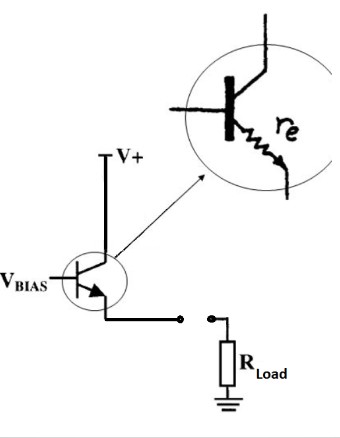
I'll just gather up what you may have already learned from the comments. Let me start off by saying... yes, you are approximately correct. The output impedance in the configuration shown is approximately \$r_e\$. G36 specifically addresses this. (This value does depend on the operating point.)
A way to see this is to imagine that the base voltage is set by a voltage source (with zero impedance) and that a hidden emitter voltage exists which is a set voltage difference away from that base voltage. This hidden emitter voltage is actually a voltage source, also with a supposed zero impedance.) Between that hidden emitter voltage source is a tiny resistor, \$r_e\$, that acts if it were part of a voltage divider formed by it and your external load.
It is modified by any base impedance, though. If that exists (and most small signal BJTs will have an intrinsic base resistance on the order of \$10\:\Omega\$), you have to translate that base impedance to the emitter. This is done by dividing the base impedance by \$\beta+1\$ and adding that result to the value of \$r_e\$. The final equation might look like:
$$R_\text{OUT} =\frac{k\: T}{q\:I_\text{E}}+\frac{R_\text{B}}{\beta+1}$$
where \$I_\text{E}\$ is the operating point.
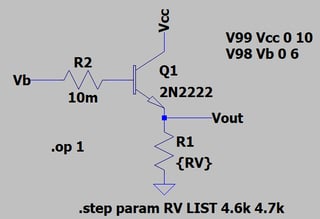
A way to test this in LTspice is to use a circuit like this:

(I've used a picture rather than the schematic editor so that you can see everything I used to generate the next bit of information.)
When you run the above spice simulation, you will get something like the following:

You can see on that plot that I've "dragged out" an area rectangle with LTspice and that LTspice automatically will calculate the slope (resistance) for you. Here, if you look at the text shown near the bottom center of the plot, you can see that it computes about \$22.7\:\Omega\$ for the slope.
Also easily seen, is that the center point of the emitter current is about \$1.15\:\text{mA}\$. Plugging this into the usual equation, we get \$\frac{26\:\text{mV}}{1.15\:\text{mA}}\approx 22.6\:\Omega\$. This is consistent.
Note that I'd said you also have to take into account the base resistance? The 2N2222 model I'm using says "RB=10." So this means our base resistance, reflected to the emitter, is about \$\frac{10\:\Omega+10\:\text{m}\Omega}{\beta=200+1}\approx 50\:\text{m}\Omega\$. So this would mean a slope that is still closer to what the above spice measurement suggested, or \$22.65\:\Omega\$. And frankly, I'm not sure how precisely I set my cursors there, so I would call this a match (to within known error bounds.)
Note that I'd inserted a dummy resistor above? \$R_2\$? If you change that resistor's value to \$1\:\text{k}\Omega\$, and run LTspice again and drag out that rectangle, you'll see that the new slope LTspice computes is about \$27.6\:\Omega\$. And \$\frac{10\:\Omega+1000\:\Omega}{\beta=200+1}\approx 5\:\Omega\$. Which, in fact, is the added difference we see here.


