I am very new in electronics, and this topic is bothering me.
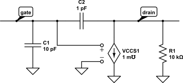
I want to know what a small signal is and how to draw the small signal equivalent of a JFET with common source.
I am very new in electronics, and this topic is bothering me.
I want to know what a small signal is and how to draw the small signal equivalent of a JFET with common source.
'Small signal' is where variations in voltage and current are so small that we don't explore the non-linear parts of the device V/I curve.
At any a given bias point, we forget about any curvature and take the gain, gm, output impedance or whatever to be given by the tangent to the curve at the operating point, and so are consequently constant.
Conversely, in 'large signal' operation, gain depends on the signal magnitude, and so we can't use linear tools.
This is something that confused me for a long time as well. The more mathematical approach helped me a lot.
To solve a circuit, what you basically do is take all the equations of each component, throw them in a big system and solve it. This is quite easy if all the equations are linear, i.e. in the form \$y = ax+b\$.
While this is true for resistors, capacitors, inductors, and for all the linear (duh) components, this is not true for example for a simple diode.
A model often used for the diode is no current if reverse biased, no voltage if positively biased. This function is not linear if you look at it together, but actually is linear if you take only a small area (a neighborhood) around the bias point. After all, the transfer function is made of two lines :)
With a diode you try to guess the zone it will be working into, you calculate the operating point, if you manage to do that there is a neat theorem that ensures that one and only one solution always exist, so you know you guessed right.
With any other non linear component you do the same, you guess where it will be working, throw in the linear model, solve the circuit, check that your assumptions were right, profit.
What are those linear model then? What is this all about?
In math language, what happens is that you calculate the first order Taylor expansion of the equations, around the bias point. You then substitute the real equations with their linear approximation, and use the standard tools to solve the circuit.
Of course you are introducing errors. The bias point is just a bias, the signals change... But if they do not change much, we call them small signals and we use the first order approximation.
I will not draw a model of a jfet because it is something that in my experience is given by the teacher, or at least found. The linear model of a FET is not something I expect to be able to extract, but rather an instrument that I use to solve circuits.
Ignoring any lead inductance and ignoring thermal noise sources, here is a small signal JFET model

simulate this circuit – Schematic created using CircuitLab