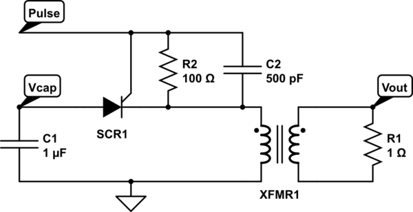
I came across an old circuit from work that discharges a capacitor (C1) into a step-up transformer to a low-impedance load. This event is triggered by a pulse into an SCR, whom has a parallel RC filter across its gate-cathode terminals. Both the Pulse amplitude and the capacitor's voltage may be in the 12V to 30V range, but they may not be equal.
I can fathom the filter capacitor (C2) -- this may prevent high-frequency noise from prematurely triggering the SCR -- but I cannot imagine the use of the resistor (R2).
Thoughts
- Perhaps R2 simply provides a bleed path for C2? That way, after
Pulsehas gone back to 0V C2 doesn't hold the gate open longer. But from what I've seen, C1 discharges in the microsecond (or less) timescale whereasPulseis high for a few milliseconds -- long after the SCR's holding current has diminished.
That's the only thought I have so far. It just seems like R2 would bleed some current from the SCR gate's and load down the Pulse supply more than necessary. Can anyone think of a reason that it's in there?

simulate this circuit – Schematic created using CircuitLab
