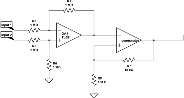
All of the designs I have seen for adding hysteresis to a comparator (Schmitt triggers) assume that one of the two inputs to the comparator is set at a fixed reference voltage
Most generally, the hysteresis effect is obtained by adding a programmable voltage source in series with one of the inputs. The polarity of the voltage is controlled by the polarity of the output. The resulting feedback must be positive, otherwise the comparator will oscillate.
The typical implementation uses a programmable current source to drive a current into a resistor in series with one of the inputs. That's the resistor R1 in the schematic diagrams below.
Furthermore, the typical implementation uses a resistor connected to the output as the source of the hysteresis current.
In such typical design, when the positive input is not exactly in the middle between the output voltage levels, the hysteresis is asymmetric about IN+. This is problematic when the reference voltage cannot be freely adjusted to remove the asymmetry, e.g. if it is an external voltage, or a sensor output.
If the comparator's output voltage swing is large compared to the range of the variable signal on the positive terminal, then a resistor may well be an acceptable approximation of a fixed current source.
If not, then a fixed current source will do the job. First, let's see what currents are driven through R2 into R1 in a conventional comparator-with-hysteresis:
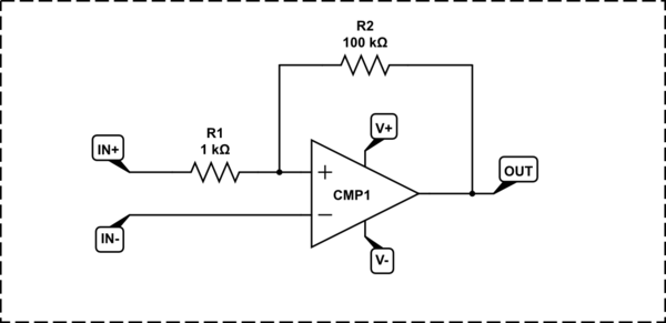
simulate this circuit – Schematic created using CircuitLab
$$
I_{H+} = {V_+ - V_{IN-} \over R_2} \\
I_{H-} = {V_- - V_{IN-} \over R_2}
$$
When the supply voltages \$V_+\$ and \$V_-\$ are symmetric about \$V_{IN-}\$, then the hysteresis currents are equal in magnitude. Otherwise, to get equal hysteresis thresholds both ways, R2 has to be split into two resistors, of different values, selected with diodes: one for each output polarity, so that the current flowing from the output through the resistor into R1 is the same for either output polarity.
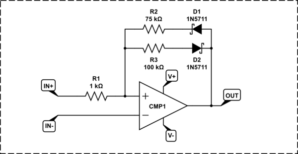
simulate this circuit
When \$V_{IN-}\$ has a large enough range, R2 has to be replaced with a current source. The current source's polarity is selected by the output polarity, and the hysteresis "brackets" are symmetric about the difference voltage \$V_{IN+} - V_{IN-}\$.
A simple source would be a cascode stage:
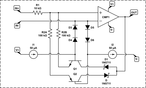
simulate this circuit
The comparator's output controls a +/- 1 diode drop voltage across R2.
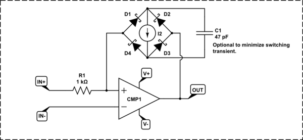
Instead of driving a fixed voltage across R2, we could switch a current source directly into the positive input:
simulate this circuit
I2 would could be an LM334 or a fixed-current diode. It can be any other suitable current source, as long as it is fast enough not to destabilize the comparator. D1-D4 should be a low-capacitance, low-current RF Schottky diodes like 1N5711.
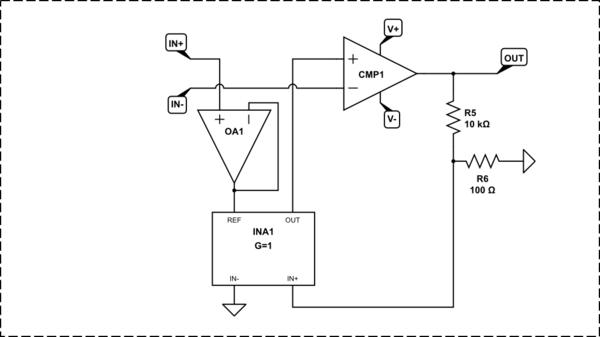
It is, of course, possible to use some other design for the programmable voltage source in series with the input. For example, you could use an instrumentation amplifier:
simulate this circuit
Of course, once you get an instrumentation amplifier involved, you may as well use it directly, as Whit3rd suggested in their answer.
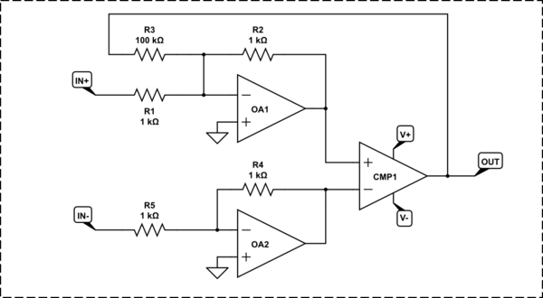
But we don't need a full-blown difference amplifier. We only need to make the voltage fed into R2 symmetric about IN+. A pair of summing, inverting op-amps does the job:
simulate this circuit

