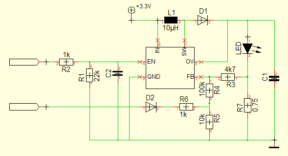
I am trying to reverse engineer an LED driving circuit. The schematic I generated from analyzing the board looks as follows:
The main circuit is this one: https://www.monolithicpower.com/pub/media/document/MP3202_r0.91.pdf
From the datasheet I understand that the FB pin is regulated to 104mV. The currently mounted LED needs a max. current of 140mA. However I am not sure if R7 is the only resistor influencing the max. current through the LED? If yes, this would result in 138mA? The input signal on the left is generated by a Microcontroller and only used for dimming?
Now I need to modify the circuit so the current is max. 60mA only. So is the only modification I have to do to change R7 to 1.75 Ohms?
I am sorry if this seems to be a silly simple question...

