0
\$\begingroup\$

I would like to make some LED lamps for night use, therefore at low intensity, just enough to see where you are walking, but almost without waking up. ;-)
It should only turn on when it detects movement and turn off after a certain time.
It must work at low DC voltage (because it is common to have small unused power supplies or easy to build a battery pack).

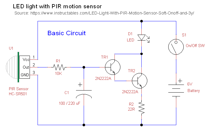
The basic circuit:
Source: https://www.instructables.com/LED-Light-With-PIR-Motion-Sensor-Soft-Onoff-and-3y/

enter image description here

Among the many circuits available on the net I chose this one, for a few reasons.
Employs a common PIR sensor, requires few components and appears set to not consume more than necessary. Not least and unlike many other similar circuits, it includes an RC (Time Constant) filter for soft-on, soft-off functionality, which I'd like to keep.

Unfortunately, the author does not explain in detail all the calculations made.
Simply I'm not experienced enough to do without it.

So I would like a small guide that highlights the right procedure, formulas and calculations to define the value of the components, for a specific LED array. How to adapt the circuit to a given load avoiding waste of current, and perhaps how to verify that it works in the best conditions.

The first revision of the basic circuit, should have:

Basic parameters:

  • HC-SR501 PIR sensor for motion detection.
  • Use of standard 5 mm. LEDs (see the table), single or LED array (always of exactly the same type of LED)
  • Regulated DC power supply between 5 and 12V (15V max.), chosen according to the number of LEDs used.
  • Soft-on, soft-off function (RC Time Constant filter).

enter image description here

Notes and Questions:

  • The Author used the BJTs he had (2N2222A). The NPN transistors I have are: BC547B/C, BC548B/C (all, max 100 mA), PN2222A (500 mA), MPS2222AG (600 mA) and SS8050 (1.5 A).
    Among them, which ones would be the more suited for this circuit?
  • Since in a Darlington pair it's the second transistor (TR2) that does the hardest work, is it better to use different transistors or to keep an identical pair anyway, perhaps to simplify the calculations?
  • My multimeter can measure the hfe of NPN and PNP transistors. I guess this can help.

Circuit Rev. 2

Thinking about a second revision, I would like to know how to add an LDR photoresistor to detect ambient light and activate the circuit only below a certain threshold. I've seen many examples, but I don't know how to integrate it into this specific circuit.

Thank you in advance.

\$\endgroup\$

1 Answer 1

1
\$\begingroup\$

I don't think battery power is very suitable for this circuit.

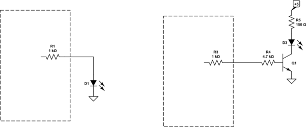
Just enough light to see- you may not need a Darlington at all, in fact you may be able to drive the LED directly from the module. There is apparently a 1K resistor in series (check that) and try just an LED to ground. A few mA into a modern bright LED produces quite a bit of light in a dark room. If you need more, a single transistor and a series resistor on the LED should be fine.

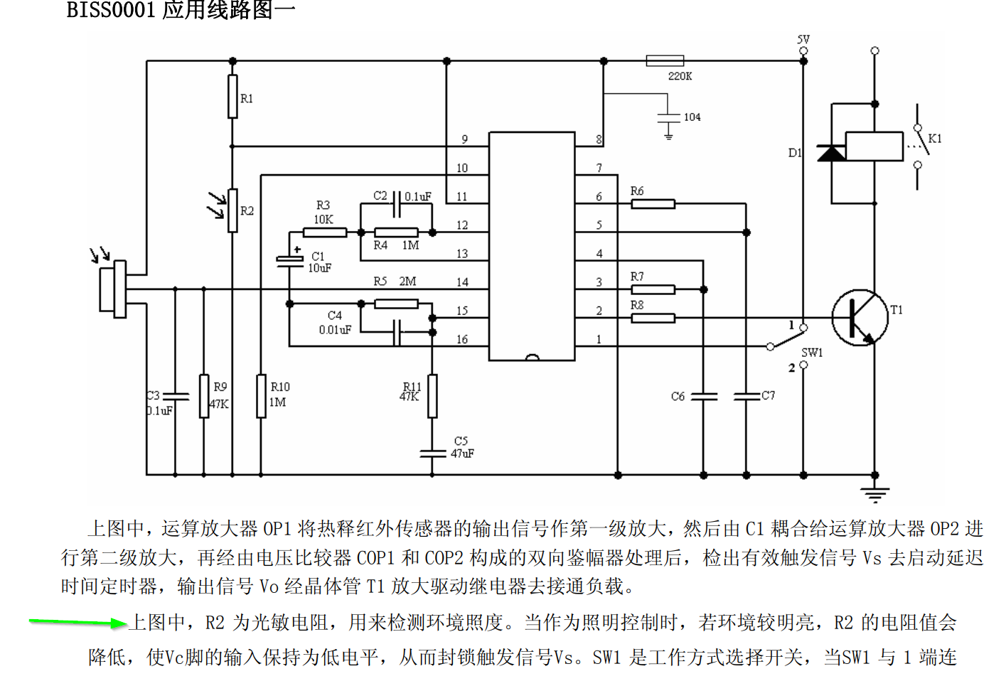
As far as using an LDR, if you refer to the datasheet for the Shenzhen Silvan BISS0001 chip used in these modules you will see the suggested circuit:

enter image description here

R2 is the LDR, R1 sets the threshold resistance. The light is disabled if the voltage at pin 9 is less than approximately 0.2Vcc. The modules appear to have pads for the LDR and a 1M resistor for R1, so you can locate the pads and add the LDR if it is not present. Check that the 1M resistor is present.

There are some English datasheets for the chip, but many of them seem to be incomplete.

schematic

simulate this circuit – Schematic created using CircuitLab

Any of those transistors you mention will work in this circuit. I made the LED current around 13mA and the base current about 1/20 of that.

\$\endgroup\$
4
  • \$\begingroup\$ @user263983 PIR sensor with fresnel is the basic function of the module. OP requests LDR disable when ambient light is present, a standard function of the chip. \$\endgroup\$ Commented Mar 16, 2021 at 13:14
  • \$\begingroup\$ Hi Spehro, Thank you so much for the tips. I didn't know it was possible to integrate an LDR directly into the PIR board. I'll try as you suggested. Unfortunately, LDR aside, I'm still at square one. I'm probably much less experienced than you think (or what I think...:-) I really need a mini guide to this circuit, with formulas and practical examples, I'm afraid. \$\endgroup\$
    – Overlights
    Commented Mar 17, 2021 at 10:24
  • \$\begingroup\$ To answer your question, I have verified my PIR board. It shows a 1.5K resistor on the output. The following RC "Time Constant" filter that I would like to keep (10K res + 100uF cap) further reduces the current based on TR1, but by how much? What formula do I use to calculate it? Then... How can I adapt these basic conditions to a particular combination of LEDs? How do I choose the most suitable supply voltage? What formulas do I use to calculate the gain of the single transistor or the overall gain of the transistor pair (TR1 + TR2)? How do I calculate the optimal value of R2? \$\endgroup\$
    – Overlights
    Commented Mar 17, 2021 at 10:26
  • \$\begingroup\$ Can we give a practical example? Let's say I want to power a set of 3 Kingbright WP7083 LEDs (If 20mA, Vf 3.2V), so a total of 9.6V at 20mA. It's correct? The next step is to choose the power supply voltage? So at least 9.6V + the voltage drops of the two transistors? And then? \$\endgroup\$
    – Overlights
    Commented Mar 17, 2021 at 10:26

Your Answer

By clicking “Post Your Answer”, you agree to our terms of service and acknowledge you have read our privacy policy.

Not the answer you're looking for? Browse other questions tagged or ask your own question.