0
\$\begingroup\$

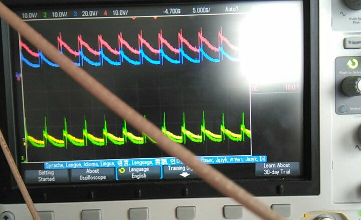
I have the following waveform from a Radar thats IVQ-3005 https://www.innosent.de/fileadmin/media/dokumente/datasheets/180222_Datenblatt_IVQ-3005.pdf

That Radar is using the PLL ADF4158 http://www.analog.com/media/en/technical-documentation/data-sheets/ADF4158.pdf

I'm using a sawtooth as modulating carrier signal, what is in the following picture is a detected wall.

Why the waves are not real sin waves ?

Is that a problem of the gain of the IF signals that is controlled by a digital potentiometer ?

Or is it a problem of the generation of the sawtooth signal ?

enter image description here

Note that the signals are I1, Q1, I2, Q2

\$\endgroup\$
5
  • \$\begingroup\$ Why the waves are not real sin waves ? Why do you expect a sine wave? Maybe the signal is reflected by more that just the wall, that would mean multiple signals. Maybe you should take a step back and figure out how the system is supposed to work instead of guessing what it can be when you do not see what you think you should see. \$\endgroup\$ Commented May 25, 2018 at 8:07
  • \$\begingroup\$ if there are multiple signals that are reflected, can you give an explanition of why the signal looks like that ? \$\endgroup\$ Commented May 25, 2018 at 8:16
  • \$\begingroup\$ Can you show me a graph (hand drawn is OK) of transmit frequency vs time? Typically, FMCW uses a linear frequency ramp (although it doesn't have to). So the start frequency is the lowest frequency (usually) and the end frequency is the highest frequency. The bandwidth of the chirp is (end frequency) - (start frequency). A linear chirp means that the frequency increases at k MHz/usec, where k is constant. Is that what you are transmitting? A linear chirp? \$\endgroup\$
    – user57037
    Commented May 25, 2018 at 20:06
  • \$\begingroup\$ Yes I'm transmitting a sawtooth \$\endgroup\$ Commented May 25, 2018 at 21:27
  • \$\begingroup\$ What is the start frequency, what is the end frequency, and what is the time duration of the ramp from start to stop? What is the distance from the antenna to wall? Did you try connecting the TX to RX using a delay line and attenuators? That might be a good idea. But add plenty of attenuation. \$\endgroup\$
    – user57037
    Commented May 27, 2018 at 6:15

2 Answers 2

0
\$\begingroup\$

It looks like you are amplitude modulating the carrier at a frequency much lower than the carrier frequency. That is not FMCW. The carrier sine wave is not there because your oscilloscope sweep rate is set to see the amplitude modulation frequency and not the carrier frequency.

\$\endgroup\$
3
\$\begingroup\$

Why the waves are not real sin waves ?

enter image description here

I'm using a sawtooth as modulating carrier signal

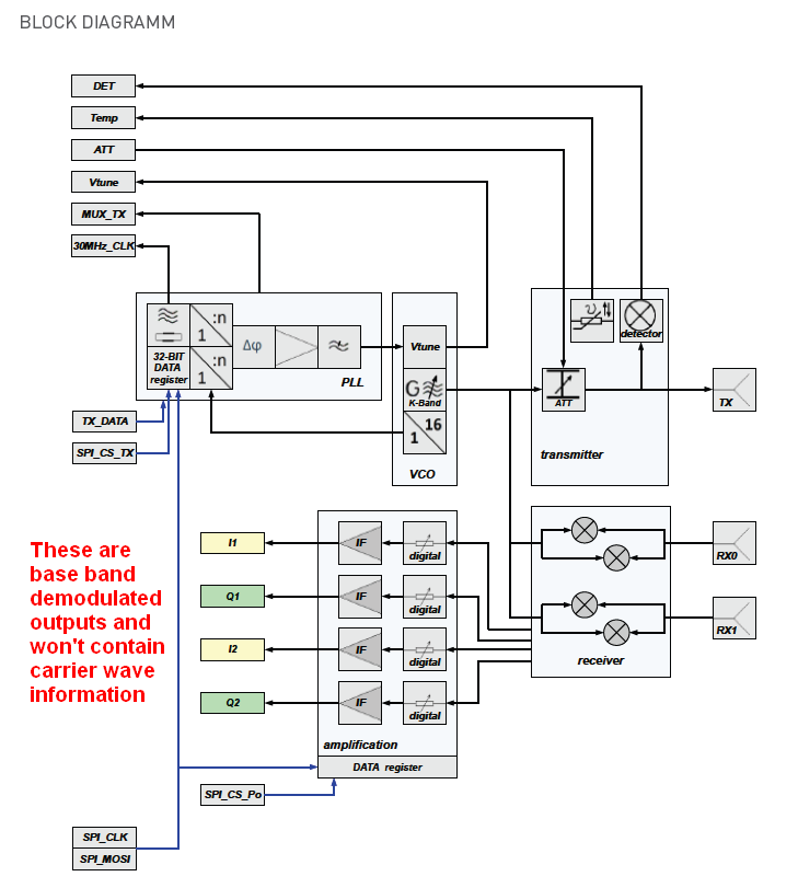
They look like sawtooth demodulated data to me.

\$\endgroup\$
7
  • \$\begingroup\$ so I need to add I1,I2, Q1+Q2, then do FFT complex on that result ? \$\endgroup\$ Commented May 25, 2018 at 8:50
  • 2
    \$\begingroup\$ I'm no expert on how to use that module. I was only able to see that your question was based on the belief that you might be expecting to see a carrier when clearly the picture tells me that base band data is what you will see. Somewhere in the data sheet they should tell you how to use (say) Q1 and Q2 either combined or differential possibly. \$\endgroup\$
    – Andy aka
    Commented May 25, 2018 at 8:52
  • \$\begingroup\$ Baseband of an FMCW would be a sine wave, or a combination of sine waves. One frequency for each backscattering target. Note how the RX is mixed with the TX. Because of the chirp nature of the signal, the RX is a lower frequency than the TX. So when they are mixed, and LPF'd, the result is a sine wave whose frequency is proportional to the distance to the target. \$\endgroup\$
    – user57037
    Commented May 27, 2018 at 6:14
  • \$\begingroup\$ @mkeith he modulates with a sawtooth so baseband is a sawtooth primarily. \$\endgroup\$
    – Andy aka
    Commented May 27, 2018 at 8:46
  • \$\begingroup\$ Maybe I am missing something. I was assuming frequency modulation. But if it is amplitude modulation, then sure. I agree. And in that case all my comments on this thread are wrong. \$\endgroup\$
    – user57037
    Commented May 27, 2018 at 17:31

Your Answer

By clicking “Post Your Answer”, you agree to our terms of service and acknowledge you have read our privacy policy.

Not the answer you're looking for? Browse other questions tagged or ask your own question.