please explain this why did he used LT1637 amplifier and transitor in circuit
-
5\$\begingroup\$ Please take a moment to think about P=I^2*R. \$\endgroup\$– winnyCommented May 29, 2018 at 13:00
-
2\$\begingroup\$ "He" used the LT1637 because it is taken out of the datasheet of the LT1637 and is just a sample circuit... \$\endgroup\$– ArsenalCommented May 29, 2018 at 13:54
2 Answers
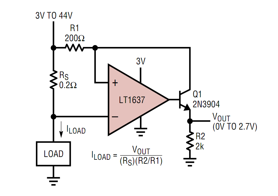
This circuit works as follows:
I load flows through Rs and creates a voltage V(Rs).
The opamp is configured such that it will try to make the voltage between its + and - inputs zero. If the opamp can manage to do that then the voltage across R1 will also be V(R2), the voltage is copied.
Since R1 has (in this case) a 1000 times larger value than Rs, the current I(R1) through R1 will also be 1000 times smaller! That current comes from the supply and flows through R1 into Q1.
The opamp controls the base such that Q1 is biased such that this current I(R1) can flow through Q1 and into R2. The voltage across R2 will simply be I(R1) * R2. There's actually slightly more current flowing into R2 (the base current needed for Q1) but we can assume that Q1 has a large beta so we can just ignore that current.
So Rs converts the load current into a voltage, that voltage is copied and the resulting current is fed into R2 resulting in a voltage.
The values of the resistors are chosen such that the resulting currents are "reasonable", meaning easy to handle with an opamp and a transistor.
Suppose we made R1 also 0.2 Ohms, also suppose Iload is 1A then I(R1) would also be 1 A. The total current into the circuit would be 2 A ! Q1 would need to be a big power resistor and it would need a heatsink. 1 A into R2 would give 2 kV, that's not practical so we would have to lower the value of R2 to 2 Ohms. R2 would need to be a power resistor as it will dissipate 2 W.
Do you see how giving R1 a much higher value results in a massive power consumption reductions?
-
\$\begingroup\$ why did he choose the resistance R1 1000 times more than Rs? \$\endgroup\$– rajeshCommented May 30, 2018 at 14:03
-
\$\begingroup\$ True or false? This circuit only works when that ratio is 1000. Wat do you think? \$\endgroup\$ Commented May 30, 2018 at 14:09
-
\$\begingroup\$ ya true it only works in that case \$\endgroup\$– rajeshCommented May 30, 2018 at 14:17
-
\$\begingroup\$ can you explain the formula I load? \$\endgroup\$– rajeshCommented May 30, 2018 at 14:18
-
\$\begingroup\$ ya true it only works in that case WRONG the circuit can work for almost any ratio. I give an example of the ratio being 1:1 instead of 1000:1 in my answer. At 1:1 the circuit is much less (power) efficient but it will still work. No, not going to explain the formula, you can do that yourself. Only basic circuit knowledge is needed. \$\endgroup\$ Commented May 30, 2018 at 14:27
To answer the part that Bimpelrekkie didn't ... why did he use the LT1637?
Note that this circuit assumes a common-mode input voltage range of up to 44V with an opamp running from a single 3.3V supply rail.
Check the common-mode input voltage range on any opamp you're interested in using, very carefully, before trying this stunt.
I expect you'll find the LT1637 (datasheet should be linked in the question) allows it ... and I expect you won't find many other opamps that will.
Which means ... yes it's a stunt, which is why it was featured in the datasheet. (And it seems we've had this circuit pop up in a question before)
-
\$\begingroup\$ could you please answer, why did he used transistor in the circuit? \$\endgroup\$– rajeshCommented Jun 18, 2018 at 17:37
-
\$\begingroup\$ The other answer covers that nicely. \$\endgroup\$– user16324Commented Jun 18, 2018 at 18:17

