I have a thermocouple with one end connected to +24V. I want to be able to read the voltage (-5mV - +20mV) on it using a 3.3V ADC. The most reasonable solution I see is lowering the voltages using resistor dividers, than two voltage followers and a differential amplifier (like here: https://electronics.stackexchange.com/a/93467/61946).
I could also power the op-amp from a higher voltage rail, though that would mean constraining the output voltage in some other way.
Is there a simpler solution I am missing?
-
\$\begingroup\$ those 0.1% precision resistors are going to blow your budget. \$\endgroup\$– Jasen Слава УкраїніCommented Dec 15, 2018 at 19:57
-
\$\begingroup\$ I will be calibrating the sensor from known temperature + voltage pairs and curve fitting, so as long as the output is a 1st or 2nd degree function of the input I'm fine, I don't need exact values. \$\endgroup\$– ChumanistaCommented Dec 15, 2018 at 19:58
-
\$\begingroup\$ thermal stability of the amplifier/offset circuit is an issue too. \$\endgroup\$– Jasen Слава УкраїніCommented Dec 15, 2018 at 20:00
-
\$\begingroup\$ It's not a known temperature thing -- it's that if you use a ground-referenced amp then you need super-precise resistors. \$\endgroup\$– TimWescottCommented Dec 15, 2018 at 20:32
-
1\$\begingroup\$ See this Q&A electronics.stackexchange.com/questions/377058/… for an unusual opamp (LT1637) which allows common mode input voltages far above its supply rail - up to 44V. Maybe it can be adapted for your application? \$\endgroup\$– user16324Commented Dec 15, 2018 at 23:04
5 Answers
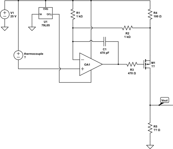
This is a suggestion only. Do a precision voltage-to-current conversion using 25V as your "ground", then do the rest of the work ground referenced. None of the component values I show should be trusted. R1, R2, R4, and R5 set the gain. You need to choose a part for OP1 that works decently with it's common mode voltage at or close to the positive rail -- even with rail-rail amps this is not a hugely common thing.
A bit of theory: M1 doesn't flow current in the gate, so the voltage that you maintain across R4 sets the current. R5 "catches" this current and turns it into a voltage (you want to buffer it immediately with a voltage follower, BTW). R3, C1, and R1 & R2 in parallel compensate the circuit for the FET's gate capacitance (use a wimpy fet with low gate capacitance). The 79L05 provides a regulated rail-5V supply for the high-side circuit.

simulate this circuit – Schematic created using CircuitLab
EDIT:
The solutions I gave previously do not compensate the cold junction temperature, which is a bit annoying. Compensating for offset is also going to be a chore.
So, in the end I would use something like a MCP9600 which is an I2C thermocouple amplifier. According to its datasheet, the thermocouple inputs common mode range includes GND to VCC, so it is possible to "hang" the chip from +24V as suggested by Tim Wescott, by using a negative voltage regulator having its GND pin tied to 24V and IN pin tied to GND.
Now you have to voltage shift the I2C output of the MCP9600 back to ground, which is annoying... or requires a USB isolator chip. It would be better to use a SPI interface chip, which does not have bidirectional pins, and is therefore a lot more practical to level shift, but I couldn't find one which supports an input common mode range including VCC (MAX31855 will not work).
So it looks like I'd go with MCP9600 + USB isolator.
Previous answer:
If you want a canned, one-chip solution you can use a Current-sense amplifier like AD8210, MAX4376, lots of offerings from most chip vendors.
AD8210 requires 5V supply, but MAX4376 works on 3V. These both support the 24V input common mode you have. Make sure you check the offset and mind your error budget. Check the "Current sense amp" category in mouser or digikey for lots of different models.
As far as "roll your own" goes, I'd do something like this:

simulate this circuit – Schematic created using CircuitLab
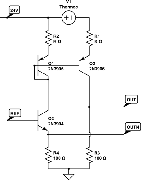
This is similar to analogsystemsrf's solution, with a dual matched PNP like MMBT3906 which is very cheap and will avoid temperature mismatch between transistors. Adjust value of R and current to keep the transistor linear at the thermocouple voltage you have. The thermocouple is "V1" here. Adjust R3 for gain. You can use any fancy current mirror you want, Wilson, base current compensation, but the basic idea remains the same: add an offset to the emitter resistors of a current mirror.
Q3 is a current source which injects a current into the mirror. Adjust voltage "REF" and both bottom resistors to a suitable value. I'd use 0.5-1mA bias current, so 1-3k instead of 100R as dwrawn.
Measuring the voltage differentially between the two OUT and OUTN points allows to get rid of the offset due to the bias current. Transistor base currents will still add some offset though.
Note: The resistance of all the wires to the thermocouple is in series with R1.
All solutions which cause current to flow through the thermocouple, like the one above, will create an offset due to voltage drop: thermocouple wire resistance x current. Please make sure this offset is acceptable. Otherwise you will need to use an opamp sitting on the +24V rail as per Tim Wescott.
-
\$\begingroup\$ I like this and the other two not-my answers for their simplicity, but you'll need to be a bit more of a transistor-circuits whiz to get the gain calculated (or you'll just need to measure and calibrate, which you'd need to do regardless). As far as I'm concerned, getting the differential output is absolutely necessary -- you want to get rid of as much offset as you can electronically, before you go chasing it in calibration. \$\endgroup\$ Commented Dec 16, 2018 at 16:45
-
\$\begingroup\$ A feature that makes me like this over mine is that while mine only works of the temperature you're measuring is hotter or colder than the circuit, this one will measure voltage excursions in the thermocouple in both directions. That means that the thing you're measuring can be either hotter or colder. \$\endgroup\$ Commented Dec 16, 2018 at 16:53
-
\$\begingroup\$ @TimWescott Thanks. I just realized it does not compensate for cold junction though, so I added one bit with MCP9600. \$\endgroup\$– bobfluxCommented Dec 16, 2018 at 17:05
-
\$\begingroup\$ I wanted to do cold junction compensation in software, measuring the temperature with something like DHT-22. Now that I look at it it might be easier to just use a high side MOSFET instead of low side and skip this whole problem. \$\endgroup\$ Commented Dec 16, 2018 at 17:15
-
\$\begingroup\$ @CodeandSolder Would be simpler to isolate the thermocouple... \$\endgroup\$– bobfluxCommented Dec 16, 2018 at 17:29
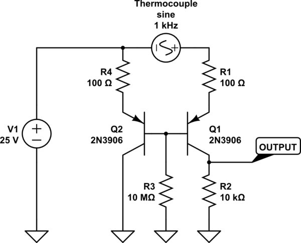
Thermistors aka temperature sensitive resistors, also used in VCO variants.
They would try to improve the "correspondence" with matched pairs & the thermistor is physically-temperature coupled to the matched pair. (temco is A brand)
-
\$\begingroup\$ It doesn't seem to work in the simulation? i.imgur.com/M9UpY3u.png (I changed the fuse to a voltage source) \$\endgroup\$ Commented Dec 16, 2018 at 13:08
-
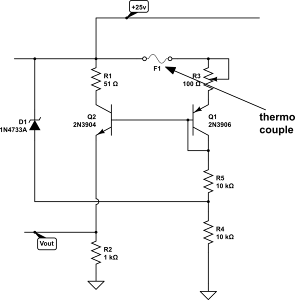
1\$\begingroup\$ That does seem to work pretty well, could you link to somewhere I could learn about how this works? I haven't seen this way of connecting transistors before. Is the model relevant or are ant PNPs OK? \$\endgroup\$ Commented Dec 16, 2018 at 14:04
-
\$\begingroup\$ Also: This leaves quite a bit of DC offset, this could be solved with an op-amp after this, right? \$\endgroup\$ Commented Dec 16, 2018 at 14:06
-
\$\begingroup\$ Put a resistor in the tail of Q2 that matches the resistance of R2, and feed that into a differential amplifier. The real shortcoming of this circuit is that the base current of the pair is going to vary a lot over part variations and over temperature, so you can't be sure that your output voltage won't rise above your low-voltage circuit's power rail. The suggestions that use current mirrors won't have that problem. \$\endgroup\$ Commented Dec 16, 2018 at 16:49
-
\$\begingroup\$ @CodeandSolder Sorry, no, I don’t have a good reference to link to explain how this works. And yes, any PNP transistor pair (ideally a matched pair) should work, as long as the \$V_{CEO}\$ is high enough. \$\endgroup\$ Commented Dec 16, 2018 at 17:01
-
\$\begingroup\$ @TimWescott Yes, peufeu’s suggestion may work better than mine. \$\endgroup\$ Commented Dec 16, 2018 at 17:02


