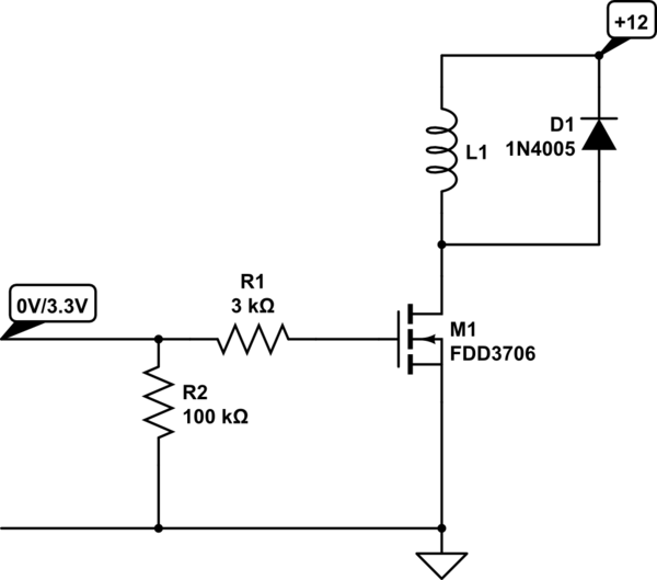
If you think as software engineer could be able to handle electronics as you say you should, I started saying a big NO.
If you have knowledge using TDD, I will show you how to deal with electronics using TDD as software engineer.
RED-GREEN-REFACTOR.
In electronics, we play all the time with tests. A datasheet is, in fact, the design tests converted into a human readable values, expected output for given and very known input.
Think your Raspberry Pi as a piece of software delieves data. The data is being processed by various elements to make a desireable result.
Unit testing comes in hand.
You want to put a transistor in power switch mode. If you put a GPIO on, the solenoid starts, and if you put your GPIO off, your solenoid stops.
Things you need to deliver to the transistor you want:
- MOSFET: the MOSFET transistor does not need any input current, only needs a voltage between Gate and Source. You can read it from any datasheet searching "Vth". The usual is a N-MOS transistor with, at most 3.3 volts of "Vth" if Raspberry Pi delivers 3.3 volts from GPIO. You can put the output GPIO directly into the Gate without any resistor.
- BJT: the BJT needs constantly a current flowing from base to emitter. This current must be previously calculated and you must include a set of resistors between Base and GPIO to generate a intake current to the Base terminal. You need to calculate the current generated using the "Hfe" value in the datasheet to ensure your circuit will work as expected. BJT's get old easier than MOSFETs, and they degrade their properties, even the "Hfe" one.
RED
If you choose MOSFET, which I reccommend you, you must insolate the output and make the test harness outside the Raspberry.
Note: the main difference between electronics and software is the
tests: we love testing in electronics and we make all the parts the
most isolated, testable and expectable as much as we can. In my
experience between firmware and software developing, I could ensure
you the software part doesn't want any tests, only the big thing
works and move on the next project, hoping the zombie will be never
be resurrected.
Your test will fail: you don't have any voltage source. Good, you will need two: one for 3.3 volts and other one for 12 volts.
Mount the Spehro Pefhany circuit without the resistors in the gate. DO NOT PUT YOUR SOLENOID YET Use a resistor to dummy it. The resistor is your mock object.
Power on both power supplies. The order is not very important, but I recommend you the 3.3 first and the 12v, later.
Note again: NEVER DISCONNECT THE 3.3V WHEN THE 12V IS ON. That's why there are resistors there. Gate is like a capacitor that charges if leaves unconnected. If you are mocking the input circuit part, is desireable to switch between 0 and 3.3 volts.
Green
Now, you can put your voltmeter and ensure the voltage is the same as expected in the formulas.
When you put 0v, the MOSFET is in the cut zone and it will not drive any current.
When you put in the 3.3v, the MOSFET will probably be in the saturation zone (or switching zone).
If the values you measure are similar to the numerical approach, congratulations, you passed the unit tests and will be ready to the integration test.
Refactor
How it will be the refactor in electronics?
Sustitution the design with other designs covers other features
Adding new features while maintain the original ones
Change some part that becames obsolete
Did any of those sounds familiar to you? In software, you made this all the time. Or you should do.
In electronics, our work material gets old, breaks or have malfunctions over his lifespan.
And go on using the red-green-refactor cycle until you get all the parameters tested and working as expected.
I hope you enjoyed this answer. It contains related info and useful tips, not really a complete answer.

