1
\$\begingroup\$

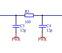
I'm wondering what's the simplest way to find the value of capacitive coupling between a cable and the main power line (230Vrms @50Hz, I'm in Europe) to use afterwards in some SPICE simulations. I know that this kind of value depends strictly to the environment and the context, but this is not the point. In my case, I have two boards connected with some cables on which flow analog signals. On one side (the first board), the cable is connected to the output of an Opamp and on the other side (the second board) is connected to the input of another Opamp configured as buffer. The grounds and the power supplies are the same on both the boards. On the web I found this model for the cable (the component values are indicative)

enter image description here

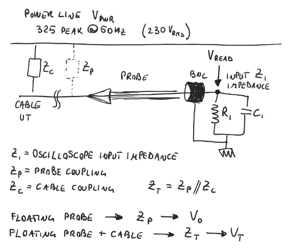
where the PWR node represents the main power line, C3 and C4 the coupling with the cable and R3 his resistance. To find the capacitance values, I thought to use an oscilloscope and simply connect the probe to the cable under test, keeping this floating in the other end. In this way, if I know the input impedance of the oscilloscope I could find the capacitance. I made a drawing to explain the concept (hope it's clear)

enter image description here

I make two measure: the first with only the probe and I see on the scope the 50Hz interference which is about some mV peak-to-peak (Vo in the drawing); then I make the second with the cable connected to the probe and I obtain a greater interference of some hundreds of mV (Vt in the drawing). With these two measurements I can find Zc.

But now came my doubts:

  • Is my method good for the cable's model I found? I think no, since the measurement are made on a floating cable which has a high impedance (oscilloscope) on one end and a 'open' on the other. In the real life my cable is connected to an opamp input (high impedance, ok) but the other end is connected to an opamp output (low impedance). Is my thinking correct?
  • Maybe the most important question: is the model above correct?

What do you think? If you have any suggestions to find (approximately, of course) this coupling value, they are welcome.

\$\endgroup\$
3
  • \$\begingroup\$ As to your second question, I quote George Box: "All models are wrong, some are useful." A model that uses lumped resistance is wrong, but it might be close enough for your purposes...if we knew what those were. \$\endgroup\$ Commented Jun 18, 2018 at 16:11
  • \$\begingroup\$ Eheheh The 'close' for me should be enough! I know that maybe my questions won't have response, but I wrote here even to know the opinion of someone. Thanks for your point. \$\endgroup\$
    – thoraz
    Commented Jun 18, 2018 at 16:25
  • \$\begingroup\$ @ElliotAlderson I edited the post with a little description of my system \$\endgroup\$
    – thoraz
    Commented Jun 18, 2018 at 16:42

1 Answer 1

1
\$\begingroup\$

Ok, as you are not seeking for an answer but rather for an opinion, here is mine:

I think you want to know the capacitive coupling because you might have some noise from the mains on your signal lines, right?

In your case, I would not care about capacitive coupling, because (if you have a problem) it might more be an inductive loop one. You wrote that both boards have the same ground and power supply, so there might be a big ground loop in your system setup? If yes, this is the most important thing you need to fix.

Edit 1:

If you want to measure capacitive coupling in your setup, i propose the following circuit: Disconnect source and load and instead short the ends of the cable. Then make a measurement with the scope and you should see no coupling voltage (see explanation in my comment below) Next, connect two 50 Ohms resistors at each end of the cable. Then make a measurement of the (coupled) voltage on the cable. Why 50 Ohms? This is just a useful measurement resistor. You can also use another value. Why both ends of the cable? Then you wont miss the inductive coupling thats also likely to happen.

From that measurement, you can calculate the coupled current source strength.

\$\endgroup\$
9
  • \$\begingroup\$ Actually I'm looking for a response :) (I hope, at least). Your opinion is very useful. Yes, I have some 50Hz noise in the signal but it is present even without ground-loop. The signals came from biopotential electrodes and the noise appears even with only the signal cable (no ground-loop, I'm sure). Your point is very useful and important, but I really would know if there is a method to find this coupling. \$\endgroup\$
    – thoraz
    Commented Jun 19, 2018 at 7:45
  • \$\begingroup\$ First of all, capacitive coupling increases with frequency. Capacitive coupling can be modeled with a current source in the signal loop. The current from this source flows through your source or load impedances, whichever is smaller. Thats why capacitive coupling can be reduced by reducing the source output impedance. If you short-circuit the source driver, capacitive coupling should disappear. \$\endgroup\$ Commented Jun 19, 2018 at 10:15
  • \$\begingroup\$ I get what you say: if i have a very low impedance on one end of the cable, the coupling effect disappears (did I get it?). Can you explain better your procedure above? When you say "short ends of the cable" you mean to ground (earth)? And so in the case using resistor (resistor from cable's end and ground)? If you make a little drawing or schematic it could be useful. Thanks a lot for your suggestion. \$\endgroup\$
    – thoraz
    Commented Jun 19, 2018 at 10:52
  • \$\begingroup\$ Yes, very small impedance on one end and the coupling disappears. By saying „short ends of cable“ i mean the same: very low impedance at the end. Sorry, no drawing, I only have mobile phone today :-( \$\endgroup\$ Commented Jun 19, 2018 at 11:01
  • \$\begingroup\$ Thank you anyway. I'll try your procedure and if no-one give me a better suggestion, I'll chose your answer. \$\endgroup\$
    – thoraz
    Commented Jun 19, 2018 at 11:04

Your Answer

By clicking “Post Your Answer”, you agree to our terms of service and acknowledge you have read our privacy policy.

Not the answer you're looking for? Browse other questions tagged or ask your own question.