0
\$\begingroup\$

I have found code for running a step motor ( https://os.mbed.com/users/XtaticO/code/sMotor/file/4b3b9e047ce3/sMotor.cpp/ ), however I am not sure if it is correct:

void sMotor:anticlockwise() { //rotate the motor 1 step anticlockwise
    for(int i = 0; i < 8; i++) {
        switch (i) { // activate the ports A0, A2, A3, A3 in a binary sequence for steps
        case 0: {
            _A0=0;
            _A1=0;
            _A2=0;
            _A3=1;
        }
        break;
        case 1: {
            _A0=0;
            _A1=0;
            _A2=1;
            _A3=1;
        }
        break;
        case 2: {
            _A0=0;
            _A1=0;
            _A2=1;
            _A3=0;
        }
        break;
        case 3: {
            _A0=0;
            _A1=1;
            _A2=1;
            _A3=0;
        }
        break;
        case 4: {
            _A0=0;
            _A1=1;
            _A2=0;
            _A3=0;
        }
        break;
        case 5: {
            _A0=1;
            _A1=1;
            _A2=0;
            _A3=0;
        }
        break;
        case 6: {
            _A0=1;
            _A1=0;
            _A2=0;
            _A3=0;
        }
        break;
        case 7: {
            _A0=1;
            _A1=0;
            _A2=0;
            _A3=1;
        }
        break;
    }


    wait_us(motorSpeed); // wait time defines the speed 
    }
}

The rest of the class works with this implementation, am I right in assuming that calling this function will move the motor 8 steps, and not one, or is there something I do not understand.

\$\endgroup\$
3
  • 1
    \$\begingroup\$ It appears to move 8 half-steps. \$\endgroup\$
    – Chu
    Commented Jun 19, 2018 at 22:18
  • \$\begingroup\$ Top understand what's going on you need a drawing of the motor wires and how the bits drive those wires (probably via an H- bridge), and what those wires go to inside the motor (i.e four electro-magnet coils). The bit sequence energizes those coils in an order that generates a rotation. \$\endgroup\$
    – vicatcu
    Commented Jun 19, 2018 at 23:38
  • \$\begingroup\$ not sure if it is correct .... correct for what? .... it would totally not work on my arduino \$\endgroup\$
    – jsotola
    Commented Jun 20, 2018 at 0:23

1 Answer 1

2
\$\begingroup\$

There are many explanations on the web for this problem with full details .

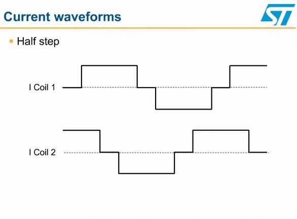
This dual coil 4 wire configuration uses bipolar current in 4 phases for 4 steps or 8 half steps or 16 quarter steps and more . Speed and torque are tradeoffs for higher resolution with fractional current steps. enter image description here

Here you can convert the state changes in current to binary logic to mean bipolar current shown here with 8 half-steps that can repeat repeated for the number of rotor+stator poles per rev. x4.

Full steps have the greatest torque.

\$\endgroup\$
2
  • \$\begingroup\$ Does this mean these 8 "microsteps" are equal to one full step? \$\endgroup\$ Commented Jun 20, 2018 at 14:47
  • \$\begingroup\$ No it means there are 4 full. steps or, phases with full bipolar current on both outputs. Half steps use half current in alternate steps of each coil to make 8 steps while micro stepping reduces the current even smaller steps to make more sinusoidal but compromises RMS current per cycle thru all microsteps \$\endgroup\$
    – D.A.S.
    Commented Jun 20, 2018 at 15:56

Your Answer

By clicking “Post Your Answer”, you agree to our terms of service and acknowledge you have read our privacy policy.

Not the answer you're looking for? Browse other questions tagged or ask your own question.