1
\$\begingroup\$

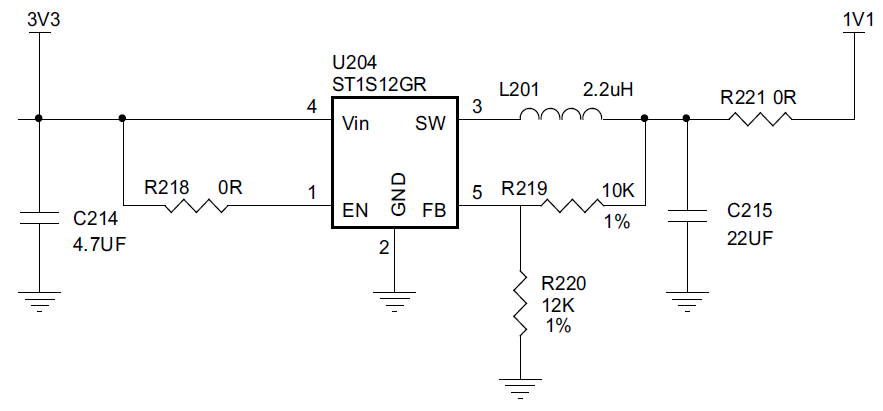
I have been given this circuit in a design guide and it does not make sense for such a complicated circuit to be implemented just to get 1.1V out.enter image description here

It requires 3.3V (input) and will give 1.1V out. The 1.1V is used to run digital functions in the chip; so I can imagine it possibly pulling too much current. Can I not use a simple voltage divider to get the 1.1V?

This image was obtained from this document (page 12).

EDIT:

This is related specifically to a system-on-chip (SoC) application.

I am trying to simplify the design without losing its functionality. Is the inductor necessary and all that.

\$\endgroup\$
3
  • 4
    \$\begingroup\$ "used to run digital functions in the chip" - in other words, this is probably the core supply voltage which runs the entire guts of the chip and is probably the largest power consumer ... So no, you can't use a voltage divider. \$\endgroup\$
    – brhans
    Commented Jul 10, 2018 at 12:16
  • 2
    \$\begingroup\$ If this circuit's only function was to make 1.1 V from 3.3 V then you're correct, a resistor voltage divider would do the job. However if you would load that 1.1 V it would drop in voltage. So obviously this circuit does more than a simple voltage divider. It provides a supply voltage meaning current can be drawn from the 1.1 V while staying at 1.1 V. \$\endgroup\$ Commented Jul 10, 2018 at 12:24
  • \$\begingroup\$ How much current do you need? You won't get away with a simple potential divider but you may be able to use a simpler linear regulator. \$\endgroup\$ Commented Jul 10, 2018 at 12:48

4 Answers 4

4
\$\begingroup\$

Can I not use a simple voltage divider to get the 1.1V?

Sure you can. It's not a good idea, but you certainly can do it.

From the data sheet, the 1.1 volt bus has a range of 1.05 to 1.2 volts. The 1.1 supply drives a number of digital lines whose state (and therefore current requirements) varies wildly, from potentially zero to some max. From page 29 of the data sheet, a maximum of 76 mA seems a reasonable number to design around.

1.05 volts over 76 mA gives a nominal digital load impedance (for high current) of about 14 ohms. To allow a 15% rise when the load is removed requires the Thevenin resistance of the voltage divider be about 1/6 of this value, or about 2 ohms. Then, roughly speaking, the divider will be a 2:1 divider with values of 3 ohms and 6 ohms. Total resistance is 9 ohms.

From this, we can calculate the power dissipated in the divider, and it is about (3.3^2)/9, or about 1 watt.

And that's with no margin. If we restrict the voltage swing on the divider to 1/2 the specified range, the power dissipation goes to 2 watts.

Assuming the specified regulator has an efficiency of 80%, at 1.1 volts out and 76 mA its power dissipation will be about 20 mW.

Plus, of course, the 1.1 volt level will vary by a few millivolts over the current range, rather than a much larger swing.

So, yes, you can use a voltage divider. You'll dissipate something on the order of 100 times as much power, but you certainly can do it.
\$\endgroup\$
1
  • \$\begingroup\$ Thank you for your answer. Your explanation and understanding it what I what looking for in this question. \$\endgroup\$
    – Gareth T.
    Commented Jul 11, 2018 at 6:01
4
\$\begingroup\$

You could use a linear regulator which would be somewhat simpler (no inductor) but much less efficient. Most of them won't go down to 1.1V because their reference is higher than that.

It looks like the current drawn by the core can exceed 130mA, so the regulator would be dissipating hundreds of mW from a 3.3V source.

The suggested switchmode regulator is very efficient and not very expensive. It uses synchronous switching so you don't even need an external Schottky.

You cannot use a voltage divider in any practical sense, the load current varies too much.

\$\endgroup\$
3
\$\begingroup\$

This is a stepdown DC/DC-converter using the buck topology. It has several advantages over a simple resistive divider:

  • It provides a regulated voltage that is not sensitive to supply voltage or load current variations.
  • It can supply several hundred milliamps of current, not something you would want to do with a resistive divider. You would primarily be heating the resistors.
  • It has a high conversion efficiency of typically over 90%

I guess you are talking about supplying the core voltage of the ST8500 chip referenced in your linked document? In the datasheet of the chip it mentions the peak power consumption of the 1.1V core voltage to be 420mW. I strongly recommend to use the DC/DC-converter and not a resistive divider.

\$\endgroup\$
1
  • \$\begingroup\$ That makes a lot of sense. \$\endgroup\$
    – Gareth T.
    Commented Jul 11, 2018 at 6:05
2
\$\begingroup\$

From the data sheet you refer I assume you are using the ST8500 modem chip.

From that we can see the 1.1V power requirements are as follows:

enter image description here

Depending on frequency this could be up to \$ (3.3 - 1.1) \text{V} \cdot 128 \text{mA} = 0.282 \text{W} \$ of losses using a linear regulator. This is certainly possible but a switch mode will have lower losses which may explain the design in the application note.

\$\endgroup\$

Not the answer you're looking for? Browse other questions tagged or ask your own question.