0
\$\begingroup\$

I have been plagued by a sensor sub-system which, when connected to my base micro-controller platform, intermittently causes issues that I would categorically associate with power sequencing issues at start-up. Some examples of things I have sometimes observed to apparently happen with this sensor subsystem attached:

  • processing board won't come out of reset / start its program
  • processing board experiences program (flash) corruption
  • processing board experiences data (eeprom) corruption
  • processing board fails to accurately read values stored in eeprom
  • processing board fails to initialize external SPI / I2C device

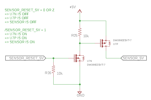
The sensor sub-system interface is a UART (RX and TX), and power is delivered to it through the processing board, which also has a FET-based high-side switching circuit gating the 5V to the unit, which gives the processor board the ability to shutdown / power-on the sensor sub-system. For your reference, here is a schematic excerpt of the high-side switching circuit.

enter image description here

That circuit has never really worked as I had intended. My firmware can, sure enough, shut the sensor sub-system down. But it can't power it back up without taking a reset itself. What a nightmare! But at least it can shut it down in the case of a communication failure mode, so I've lived with various firmware workarounds / behavioral patterns for a while. Settling for workarounds has been a curse though, and I really want to get to the bottom of it.

I've been over it in my head a lot, and I haven't been able to narrow down a root cause with certainty, so I think it's time to seriously reconsider my integration strategy in order to better decouple the power distribution between the processing board and the sensor sub-system somehow.

My system is powered by a 5V/2A AC/DC power supply that has plenty of headroom (at least 50%) for the whole system to operate. The processor sub-system is of my own design, the sensor sub-system is commercial off-the-shelf, I can't change it.

So here are some questions:

  1. What kinds of design changes would you consider in my situation?
  2. What coherent explanations are there for why my processor sub-system can't power down and then power up the sensor sub-system without taking a reset itself?
  3. What steps can I take to make my design more robust / reliable without breaking the bank (after all, it's not a safety critical system or anything like that)?

Cross-referencing tangentially related quesiton / consideration here.

\$\endgroup\$
6
  • 1
    \$\begingroup\$ What is the sensor discharge time to 0V? \$\endgroup\$
    – D.A.S.
    Commented Jul 13, 2018 at 3:26
  • 1
    \$\begingroup\$ Do you have enough decoupling capacitors on both modules? Have you 'scoped the 5V power rail while trying to power on the sensor? \$\endgroup\$ Commented Jul 13, 2018 at 4:20
  • 1
    \$\begingroup\$ A completely different direction help divide and conquer the problem. Must of what you listed at the top could also be related to some software issues in the start-up code. I'm sure you think it is unlikely. I won't argue. But one thing to do is to totally remove your application from the MCU and reprogram it with a very very simple bit of code that just accepts a power-up and toggles an I/O pin. That's it. Nothing more. Then go back and see if any of your list of behaviors go away. If so, you may have more than one problem to deal with. It's a good idea when solving hardware problems. \$\endgroup\$
    – jonk
    Commented Jul 13, 2018 at 4:59
  • \$\begingroup\$ @TonyEErocketscientist I'll have to double check, but I think I've tried as long as 10 seconds of delay after powering down the sensor sub-system before trying to power it back up and the MCU still bounces. I'm pretty sure its fully discharged by then. But I can try and measure that time, sure. \$\endgroup\$
    – vicatcu
    Commented Jul 14, 2018 at 15:32
  • \$\begingroup\$ @immibis I have no insight or control over the decoupling of the sensor sub-system module. The processing sub-system has the usual 0.1uF ceramics on all the ICs including the microcontroller and 10uF electrolytic of bulk capacitance on the 5V rail. I'll need to find a bit of time to set up a scenario where I can scope the +5V, SENSOR_5V, and SENSOR_RESET_5V concurrently, and maybe the MCU reset for good measure. \$\endgroup\$
    – vicatcu
    Commented Jul 14, 2018 at 15:37

1 Answer 1

1
\$\begingroup\$

Check the SENSOR_5V rail and +5V rail with an oscilloscope during the power-on sequence. You probably have a fast edge on the rail, possibly with ringing or undervoltage on the +5V rail during switching.
The undervoltage on the +5V rail is the most likely and would probably be caused by low ESR power supply filter caps on the sensor module. You can fix this by putting a resistor in series with the drain of the NFET. This will form an RC low pass with the gate capacitance of the PFET and slow the switching edges on the power supply output rail which will reduce the peak current requirement for charging the bypass caps on the sensor module.

\$\endgroup\$
5
  • \$\begingroup\$ what size resistor are you thinking? And do you do mean connect the drain of the NFET to the gate of the PFET with this resistor? Does it matter which side of that resistor the pull-up gets connected (NFET drain side or PFET gate side)? \$\endgroup\$
    – vicatcu
    Commented Jul 14, 2018 at 15:25
  • 1
    \$\begingroup\$ The ideal value would require analysis. Many sensor chips will have a minimum or maximum ramp time for power up (usually to insure reliable reset of the chip on power up). To keep it simple, I would start with a 1K resistor on the gate of the PFET. Putting a resistor that is not tiny on the NFET drain will decrease Vgs on the PFET (well, increase it since it is negative) which may complicate things. You really do need an oscilloscope to diagnose and correct problems like this. If this is for a product or production system, poking at it until it works is not a good strategy. \$\endgroup\$ Commented Jul 15, 2018 at 18:38
  • \$\begingroup\$ I have a 4-channel Tek DPO2014 so I can certainly probe and trigger. Just difficult to know exactly what I'm looking for. \$\endgroup\$
    – vicatcu
    Commented Jul 15, 2018 at 22:51
  • 1
    \$\begingroup\$ Put one probe on the +5V rail and another on the SENSOR_5V rail, trigger on rising edge @ 2V or so on the SENSOR_5V rail. You should see what is happening on both rails during the power-on switch event. If you don't find anything interesting, try setting the +5V rail to AC coupling and turn up the V/div for that channel, trigger @ -0.1V. A disturbance that small should not affect anything but at least you will get a good look at exactly what is going on. \$\endgroup\$ Commented Jul 16, 2018 at 23:38
  • \$\begingroup\$ Great, thanks for the tips, will definitely do that. I almost never find myself using AC coupling :-), how ... analog. FYI I've posted a follow up / tangential question after considering this answer electronics.stackexchange.com/questions/386136/… \$\endgroup\$
    – vicatcu
    Commented Jul 17, 2018 at 1:34

Your Answer

By clicking “Post Your Answer”, you agree to our terms of service and acknowledge you have read our privacy policy.

Not the answer you're looking for? Browse other questions tagged or ask your own question.