0
\$\begingroup\$

I have an input that is either floating, or grounded.

The switch is fixed, it's either open or closed. Ie, I can't replace with a double throw.

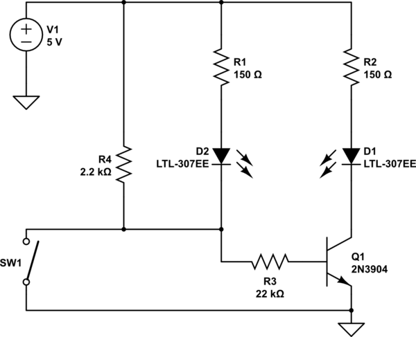
Here is the schematic / sim.

If the switch is closed, I want the lower LED to come on. If the switch is open, I want the upper LED to come on.

I feel like i'm pretty close, but that diode in there just feels wrong, and when the switch is closed you can see the upper LED stays on dimly.

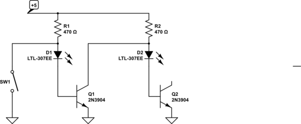
Here is my second attempt.

This one has a pull up resistor for the NPN and it has a pull up resistor for the switch. But the upper LED still is slightly dimly lit.

How do I fix that?

\$\endgroup\$
2
  • \$\begingroup\$ How about this and put switch to high with pull down for inverted output electronics.stackexchange.com/posts/comments/… \$\endgroup\$
    – D.A.S.
    Commented Jul 19, 2018 at 23:39
  • 1
    \$\begingroup\$ You need to drive one transistor from the output of the second one, instead of trying to control both from the same switch. But you only need one transistor, in fact you don't need any... \$\endgroup\$
    – Henry Crun
    Commented Jul 20, 2018 at 1:09

4 Answers 4

2
\$\begingroup\$

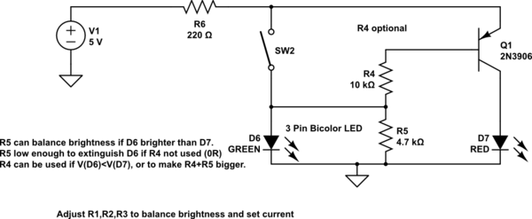
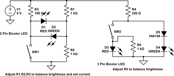
What are these "transistors" of which you speak?

schematic

simulate this circuit – Schematic created using CircuitLab

You need to adjust the resistor values to get the currents you want, and to balance the brightness of the leds, as different leds/colours have different brightnesses. (hint: you can use "simulate this circuit")

Both can be used with a single bicolor LED if you want. D4 should be a higher voltage color than D3. V(D4+D3) >> V(D3), so when SW2 closes the current goes though D3.

Note that the forward voltage of the different colors is important in these arrangements.

These arrangements work better on higher voltages, as the currents will naturally be be closer for the two leds.


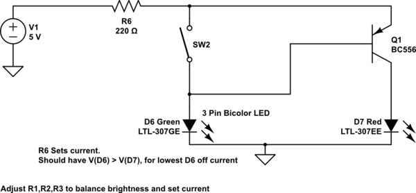
Oh, alright here's a transistor one. It's a better choice at low voltages, it can give nearly equal currents on 3.3V. R6 sets the LED current. If you use R4 and R5, then the voltage across D6 is <1V, and the D6 off current is very small.

The lower Von RED led is paired with the transistor so the voltage of both paths is more equal.

schematic

simulate this circuit

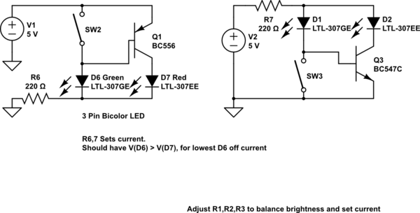
As long as Q1 has reasonable gain, neither resistor is really needed, as the off current of D6 is only 100-200uA. The more D6.Von (green) is > D7.Von (red), the less the off current will be. This arrangement works if D6=blue, D7=red, but you need R4,5 if D& blue, D6 red.

schematic

simulate this circuit

So if your switch has to have one end connected to the battery, you just move R6, and flip it all over if you want (-ve) switch.

schematic

simulate this circuit

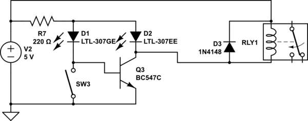
Adding a relay...

schematic

simulate this circuit

\$\endgroup\$
8
  • 1
    \$\begingroup\$ Something is seriously wrong with the transistor circuit shown. \$\endgroup\$ Commented Jul 20, 2018 at 3:04
  • \$\begingroup\$ @DwayneReid Ok you got me, what? Simulates OK for me. \$\endgroup\$
    – Henry Crun
    Commented Jul 20, 2018 at 5:26
  • \$\begingroup\$ Thank you!! These are so awesome! I think I need a transistor based one as my LEDs normally take a resistor of 100 ohms... so for the first one R3 would be something like 10 ohm, pushing 500 mA though it. The first transistor based schem is perfect...but I can't figure out how to adapt so the switch is switching either floating or ground...the schem you provided is switching either floating or +5V. How would I adapt that? Thank you! \$\endgroup\$
    – cat pants
    Commented Jul 20, 2018 at 6:38
  • 1
    \$\begingroup\$ @catpants Move R6 (its still in series limiting the current). See new cct \$\endgroup\$
    – Henry Crun
    Commented Jul 20, 2018 at 6:57
  • 1
    \$\begingroup\$ relays must have a diode across the coil, unless you want to destroy your transistor. I can't see what that circuit is trying to do. BTW, those falstead circuits are illegible to the rest of us.. \$\endgroup\$
    – Henry Crun
    Commented Jul 20, 2018 at 20:01
1
\$\begingroup\$

I'll just take a very simple approach that starts out with the obvious BJT switches and adds one more BJT in order to complete the circuit. The resulting circuit will consume a little more than either LED requires.

I noticed that you did not mention LED colors. So this obvious approach also works regardless of the color of your LEDs (assuming you stick with the \$5\:\text{V}\$ voltage source.) You can freely adjust the current in either LED, separately.

So let's start:
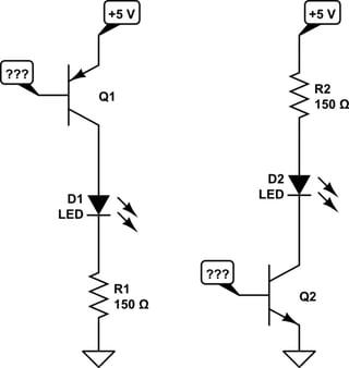
schematic

simulate this circuit – Schematic created using CircuitLab

You can see that these are just polar opposites of each other and that both are supposed to operate as BJT switches. \$R_1\$ and \$R_2\$ can be independently adjusted to provide appropriate current limiting for each LED. The BJT switches will be operated in a way that doesn't require any particular BJT type. I'm estimating \$20\:\text{mA}\$ for each LED.

Of course, the remaining problem is that there are two open (???) connections on the left side of each separate switching circuit (the BJT bases) that need to be "driven" somehow by your grounded single-pole switch (momentary or otherwise.)


To achieve that, another transistor is added. The values for \$R_3\$, \$R_4\$, and \$R_8\$ are calibrated so that the LEDs can achieve up to \$20\:\text{mA}\$ each. So you should hold near those values. The values for \$R_5\$, \$R_6\$, and \$R_7\$ are less critical. I've set them a little towards the higher end of the values you might use to reduce unnecessary wasted dissipation.
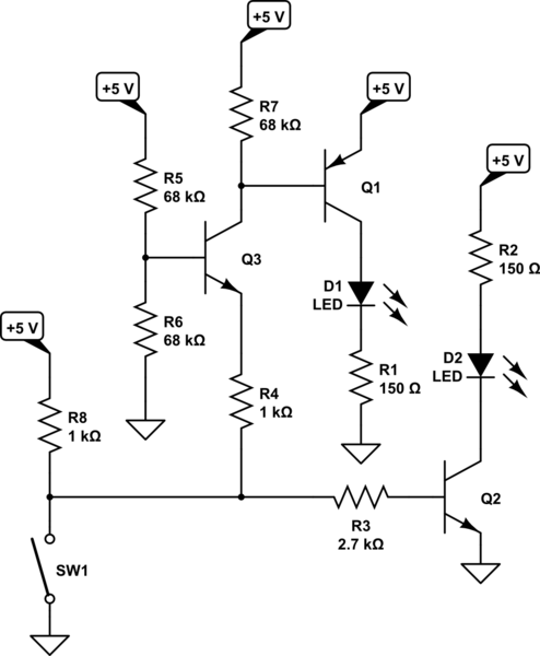
schematic

simulate this circuit

When the switch is open, \$R_8\$ works together with \$R_3\$ to supply base current for \$Q_2\$, turning it on. Also, \$R_8\$ pulls one end of \$R_4\$ up high enough that \$Q_3\$ is off and therefore allows \$R_7\$ to hold \$Q_1\$ off, as well.

When the switch is closed, the base of \$Q_2\$ is held to ground so it's now off. But the switch pulls one end of \$R_4\$ to ground so that now current is flowing through \$R_4\$, then via the emitter and on to the collector of \$Q_3\$, finally then to supply base current for \$Q_1\$, turning it on. (The purpose here of \$R_5\$ and \$R_6\$ is to provide a modest voltage divider, so that \$Q_3\$ can be either off or on depending on the state of the switch.)

Just a straight-forward approach. How it looks compared to another approach will depend on what's more important to you.

\$\endgroup\$
1
\$\begingroup\$

This problem does not need a complex solution, a very simple execution might be as follows:

schematic

simulate this circuit – Schematic created using CircuitLab

Since your switch is grounded on one side this is a straight forward BJT used as an inverter to drive the second LED. The particular LEDs show here are Vf=2V so R1 and R2 limiting at about 20mA.

With SW1 open Base current is supplied to Q1 and D1 is ON. R4 ensures there is a very low voltage across D2 so it won't glow dimly.
With SW1 closed, D2 is ON and Q1 OFF, therefore D1 is OFF.

You could even eliminate one of the resistors if the LEDs are the same Vf. If the LEDs are markedly different colors (technology) then you need both R1 and R2.

Q1 could be replaced with a single N-Channel FET if desired.

If your supply voltage is higher, then you need to recalculate R1/R2 to get the right LED current. R3 and R4 will work for supplies from 5 - 15V.

\$\endgroup\$
0
\$\begingroup\$

Here is one way (not very efficient)

schematic

simulate this circuit – Schematic created using CircuitLab

\$\endgroup\$

Your Answer

By clicking “Post Your Answer”, you agree to our terms of service and acknowledge you have read our privacy policy.

Not the answer you're looking for? Browse other questions tagged or ask your own question.