1
\$\begingroup\$

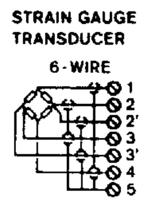
This industrial amplifier is used for force transducers and here is the wiring diagram for the 6 wire transducers: ¨ enter image description here
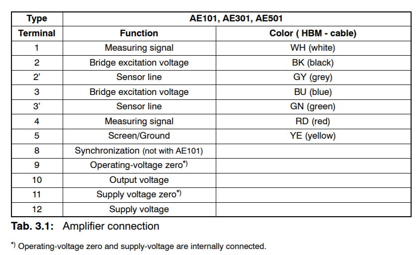
And below is the terminals for the amplifier:

enter image description here

It seems 1 and 4 terminals are the output of the Wheatstone bridge to be amplified.

I'm kind of confused why there is two connection for the excitation voltage terminals of the bridge here. As you see 3 and 3' or 4 and 4' both are same points which are separately brought to the amplifier terminals. What could be the reason for 3' and 4'?

\$\endgroup\$
1
  • \$\begingroup\$ Kelvin probes... \$\endgroup\$
    – user16324
    Commented Jul 20, 2018 at 14:01

3 Answers 3

2
\$\begingroup\$

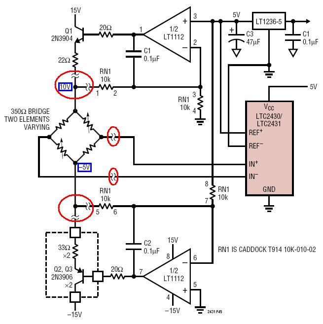
Try this picture: -

enter image description here

I've put red circles around the bridge connections and note that there are 6 bridge wires represented by the squiggly lines. The nodes marked with blue boxes are +10 volts and -5 volts respectively and these are regulated at the bridge by using feedback wires. Hence that is why you get two wires per bridge excitation node - one to drive current into the node and one for node voltage feedback thus regulation of +10 volts and -5 volts at the bridge is maintained and this means one less "error" in the measurement.

\$\endgroup\$
4
  • \$\begingroup\$ But that junction points/nodes for 3 and 3' or 4 and 4' can be at the amplifier terminal or even inside. Why do they go all the way to the bridge with "separate" wires? The feedback could be taken at any point where 3 and 4 connects. Is that because where the feedback wire is connected important because of some possible voltage drop ? \$\endgroup\$
    – floppy380
    Commented Jul 20, 2018 at 16:43
  • \$\begingroup\$ Absolutely because of voltage drop. That's the error that can only be got rid of by either using feedback to maintain the bridge voltage constant or, as Dwayne mentions, by using those extra wires for measuring that voltage and factoring that into the result. \$\endgroup\$
    – Andy aka
    Commented Jul 20, 2018 at 16:53
  • \$\begingroup\$ I use single ended system at the moment. The Wheatstone bridge is very affected from the power supply noise like 50Hz or harmonics ect. Do you prefer linear power supply or special supplies in such applications instead of SMPS? I couldn't find much info about it. Thanks anyway for the illustrated answer \$\endgroup\$
    – floppy380
    Commented Jul 20, 2018 at 16:57
  • \$\begingroup\$ I've used SMPS power supplies but specialist ones that have been designed to have other unrelated features. With a single ended bridge you will still have a volt drop up the 0 volts line and this will cause an error. It can be hard to eradicate 50 Hz noise because it can be due to several factors working together i.e. there may be no single circuit cure and multiple fixes are needed. Of course if you have low BW then you can filter the result. \$\endgroup\$
    – Andy aka
    Commented Jul 20, 2018 at 17:01
2
\$\begingroup\$

The extra +/- excitation terminal are for a Voltage Sense. When transducer cables are long, there could be IR voltage drops along the cable, messing around with your transducer sensitivity, or passing noise along. The sense lines provide a LOW CURRENT sense path (assuming they're connected to high Z inputs), telling a power control mechanism what the excitation is at the bridge, facilitating feedback control of the excitation.

\$\endgroup\$
2
  • \$\begingroup\$ How does it happen innerly? I couldnt picture what you mean. Could you provide a simple drawing illustrating what you say? \$\endgroup\$
    – floppy380
    Commented Jul 20, 2018 at 12:25
  • \$\begingroup\$ It is called "4-wire" or "Kelvin" sensing. You don't want to apply current through the same wires you are using to sense voltage. If you do, then the voltage drop in the wires due to the current will add to the voltage you are trying to measure letting to an incorrect measurement. So you apply current through one set of wires, and sense with another pair. \$\endgroup\$
    – TimB
    Commented Jul 20, 2018 at 12:35
1
\$\begingroup\$

I do things a little bit differently than the other answers but the net result is similar.

I feed the excitation inputs of the bridge from my regulated power source via low-value current-limit resistors. The bridge outputs go to the differential input of the A/D converter as normal. The Kelvin sense wires from the bridge go to the (+) & (-) reference inputs to the A/D converter.

The net result is that the A/D converter reference input is reading the exact voltage that is present on the excitation terminals at the bridge. Voltage drops on the excitation leads that feed the bridge are ignored.

\$\endgroup\$
3
  • \$\begingroup\$ +1 good way too. \$\endgroup\$
    – Andy aka
    Commented Jul 20, 2018 at 16:17
  • \$\begingroup\$ @Dwayne Reid Is what you do called ratiometric measurement? \$\endgroup\$
    – floppy380
    Commented Jul 20, 2018 at 16:45
  • \$\begingroup\$ Yes - this is a ratiometric measurement. \$\endgroup\$ Commented Jul 20, 2018 at 22:33

Your Answer

By clicking “Post Your Answer”, you agree to our terms of service and acknowledge you have read our privacy policy.

Not the answer you're looking for? Browse other questions tagged or ask your own question.