1
\$\begingroup\$

I'm relatively new to electronics and this is not my usual field of work.

For a bigger project I need to read a flow sensor's (Biotech FCH-C-PA-N) output. The output needs to be processed by an Arduino or Raspberry. The problem I have: The flow sensor's output (a square wave with varying frequency) has a Voltage between 0mV-220mV where the ~220mV represents the HIGH state.

How do I amplify the 220mV to 3.3V (RaspberryPi) or 5V (Arduino)?

I thought about using a darlington-circuit. But even with three Transistors (BC547) somehow I can't read a HIGH state at the microcontrollers input. The darlington circuit doesn't open.

enter image description here

edit: Problem solved

As stated by WhatRoughBeast this sensor works as intended without trying to amplify the signal (which was done wrong by me anyway due to a misunderstanding of the amplifying effect of transistors). It turned out that the used sensor was "FCH-C-PA" and not "FCH-C-PA-N" (I got the wrong manual by the seller). This one uses NPN open collector sinking, so WhatRoughBeast's answer is correct.

The reason why I couldn't get the correct signals at first (after plugging in the pull-up resistor) was a short-circuit at the electrical connection which was encased.

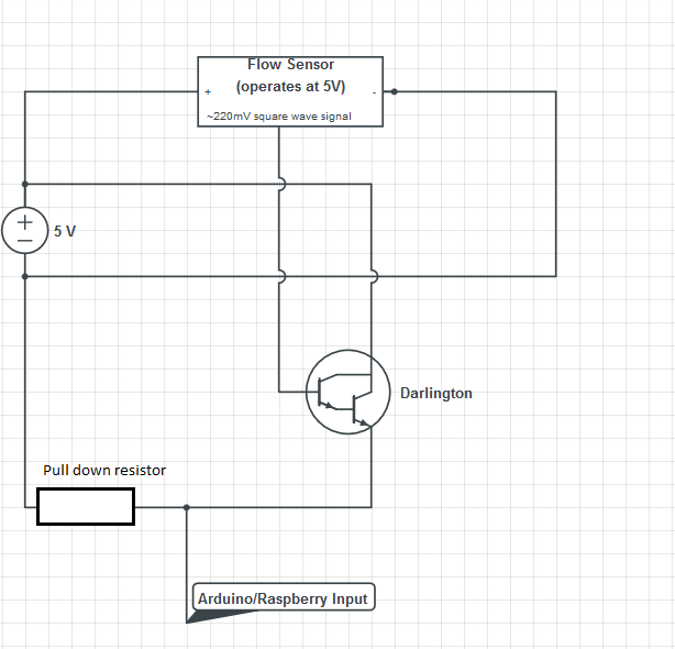
\$\endgroup\$
0

2 Answers 2

2
\$\begingroup\$

Your problem is that you have ignored the part of the data sheet which states that the sensor output is "open collector NPN". Disconnect the Darlington, and connect a 10k resistor from the sensor output to +5. The fact that you're seeing 220 mV is just an artifact of leakage.

With a 10k to +5, you'll see 0 - 5 volts pulses, and you can tie these directly to your Arduino.

And, just to make things clear, you must also get rid of your pulldown resistor.

\$\endgroup\$
3
  • 1
    \$\begingroup\$ @DeMo BioTech datasheets claim that Durchflussmesser FCH-CE-PA has open collector NPN sink output, Durchflussmesser FCH-CE-PA-N has PNP output with internal 2.2kOhm pull-up resistor. There's error somewhere. btflowmeter.com/fileadmin/PDF/Flowmeter/97478988-FCH-CE-PA.pdf and the other produktinfo.conrad.com/datenblaetter/500000-524999/… \$\endgroup\$
    – user136077
    Commented Jul 27, 2018 at 15:23
  • \$\begingroup\$ Well, OK, no problem. If a 10k to +5 doesn't do anything (other than pull the output up to +5), try a 10k to ground. If you've got a PNP output, that will work. Either way, there is no sense in trying to amplify a signal which ought to be adequate without amplification. \$\endgroup\$ Commented Jul 27, 2018 at 16:06
  • \$\begingroup\$ @WhatRoughBeast I tried to modify the circuit like you described it but sadly I still don't get the desired signal. All the arduino sees is a LOW signal. This is what my setup looks like now: Link to image. The other suggested method does not work either. \$\endgroup\$
    – DeMo
    Commented Jul 30, 2018 at 8:43
1
\$\begingroup\$
  1. A darlington is pointless here. For your purpose, there is nothing useful a darlington does that a single BJT couldn't do.
  2. You are using the transistor in emitter follower mode. That provides current gain but no voltage gain.
  3. Since the transistor is used as emitter follower, the output is lower than the input by the B-E drop. That B-E drop is larger than your signal, so you never get any output. Note that a darlington actually makes this worse since it has two B-E drops. However, the B-E drop of a single transistor would still be too big anyway.

While it is possible to amplify this signal by using a few transistors, it is easier to use a opamp. Get a opamp that is rail to rail for both the input and the output. Something like a MCP606 would probably do. I'm assuming the output of this "flow sensor" has a bandwidth well below the 150 kHz or so the MCP606 can do. Wire the opam in classic positive gain configuration.

\$\endgroup\$
1
  • \$\begingroup\$ Thank you very much. Why is it not possible to just use a single BJT as a switch in this scenario? Wouldn't a voltage applied to the base bring the resistance between the collector end emitter down to nearly 0? \$\endgroup\$
    – DeMo
    Commented Jul 27, 2018 at 12:53

Your Answer

By clicking “Post Your Answer”, you agree to our terms of service and acknowledge you have read our privacy policy.

Not the answer you're looking for? Browse other questions tagged or ask your own question.