I'm trying to learn electronics and electrical engineering through building small practical projects (toys mostly). I've been learning a ton from adafruit and spark fun, but I'm trying to branch out a bit and learn outside of their tutorials from time to time.
I have a couple of projects that I want to add sound to and provide volume control for. I had problems achieving this on my last project (the potentiometer "worked", but the volume only changed along a small portion of the pot's range and the change was very drastic).
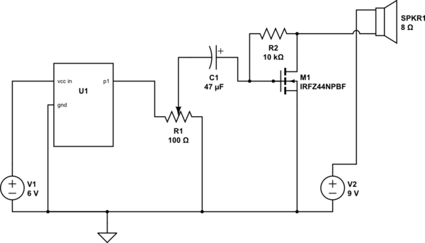
I did some searching around and found a really rough video on youtube where the maker built out an amplifier for his phone. I adapted the circuit diagram to work with tone signals I'm sending out from my adafruit micro controller and it works.
The fact that it functions is great, but I don't completely understand what's going on. This is the first time I've worked with a mosfet (which I know is a transistor and operates like the NPN transistors I've used previously) and a capacitor.
I get that the mosfet is allowing me to use the smaller 3v signal coming out of my controller (p1) to control the higher 9v power source effectively amplifying the signal but I'm a little hazy on some of the other details:
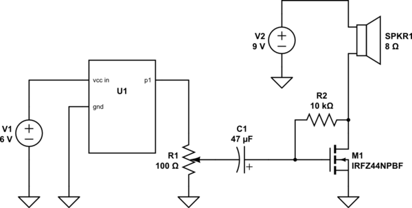
- Does this circuit look correct? (it physically works, but I don't know if I drew the circuit correctly :/ )
- What does the capacitor actually do in this circuit?
- Why do I need a resistor across the gate and drain legs?
I definitely appreciate any insight you can give.

simulate this circuit – Schematic created using CircuitLab

