0
\$\begingroup\$

(Assuming ideal elements) My friend is trying to convince me that the voltage across \$R_L\$ varies between 4 and 6 volts, says the average value doesn't decrease and stays fixed at \$5V\$ forever.
I'm not getting how this is possible:
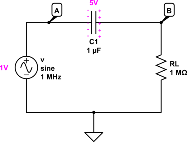
schematic

simulate this circuit – Schematic created using CircuitLab

The amplitude of the input ac signal varies between -1 and +1 volts, always less than the capacitor voltage of \$5V\$. Wouldn't the capacitor see this low voltage and start discharging?
How can the 1V input AC signal put more charge into the capacitor so that the capacitor's voltage increases, even slightly?
Does not make much sense to me.
Highly appreciate any help. Thanks!

\$\endgroup\$
11
  • \$\begingroup\$ What does "[4,6]" mean? Ditto elsewhere. \$\endgroup\$
    – Andy aka
    Commented Jun 12, 2017 at 13:41
  • \$\begingroup\$ sorry it means any value between 4 and 6 \$\endgroup\$
    – Hiiii
    Commented Jun 12, 2017 at 13:42
  • \$\begingroup\$ The say that and don't use obscure references. Your friend is wrong BTW. \$\endgroup\$
    – Andy aka
    Commented Jun 12, 2017 at 13:44
  • 1
    \$\begingroup\$ There is a DC path around the cap its going to discharge. \$\endgroup\$
    – sstobbe
    Commented Jun 12, 2017 at 13:55
  • 1
    \$\begingroup\$ Yes if you inserted a precharged cap to 5VDC, RL would see slightly less than 6V to slightly less than 4V. DC would decay as RC time constant to 0VDC. \$\endgroup\$
    – sstobbe
    Commented Jun 12, 2017 at 14:11

3 Answers 3

2
\$\begingroup\$

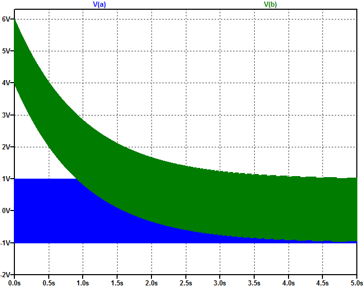
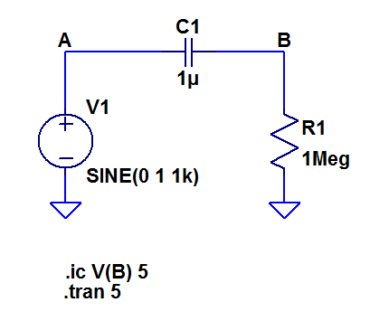
Yes, There is a DC path around the cap its going to discharge. DC response follows RC time-constant.

enter image description here enter image description here

\$\endgroup\$
2
  • \$\begingroup\$ Cool plot ! Definitely one picture is better than 1000 words! May I know which tool you're using ? @sstobbe \$\endgroup\$
    – Hiiii
    Commented Jun 12, 2017 at 14:50
  • \$\begingroup\$ @Hiiii Its LTSpice linear.com/designtools/software/#LTspice It is Free! \$\endgroup\$
    – sstobbe
    Commented Jun 12, 2017 at 14:54
2
\$\begingroup\$

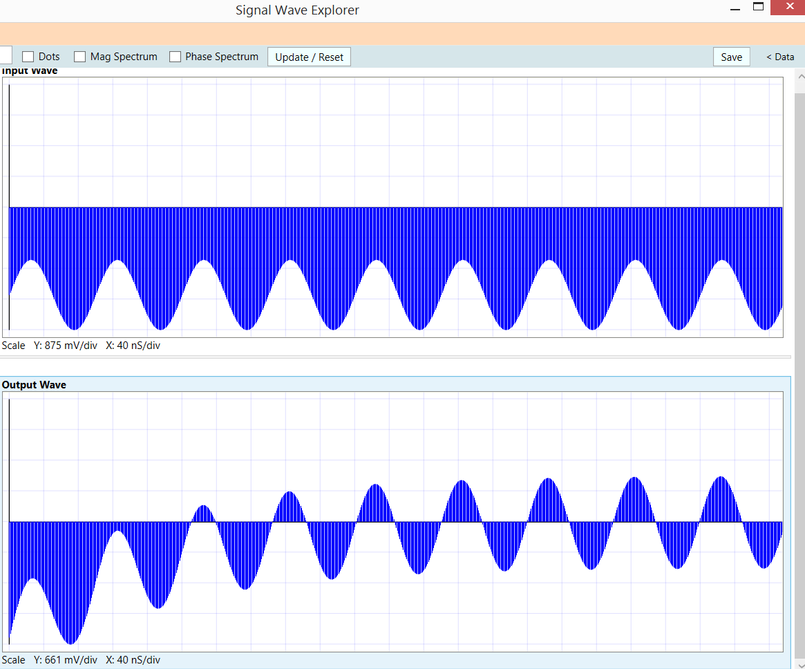
How about this, from Signal Wave Explorer: 1MHz DC-block (high pass filter), with 10MHz sin input 1volt peakpeak with 2.5 volt offset

enter image description here

\$\endgroup\$
1
  • \$\begingroup\$ May you comment what is represented by two upper graphs? \$\endgroup\$
    – MaxMil
    Commented Dec 18, 2017 at 9:07
1
\$\begingroup\$

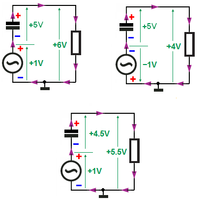
You can replace the sinewave with the square wave and now the situation will look like this:

enter image description here

As you can see the capacitor will have a path for a discharge current to flow. And after some time the capacitor reach steady state and in steady state condition, the average capacitor current is \$0A\$ over a cycle (I_charge = -I_discharge).
AC Circuit Having Only Capacitor

EDIT

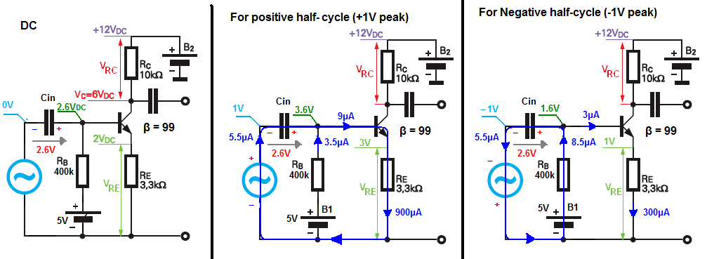
In real amp life the situation will look like this:

enter image description here

At DC the Cin capacitor is charged to \$2.6V\$

For positive half-cycle (+1V peak):

As you can see \$5V\$ source provide \$3.5μA\$ of current, but the base current needed to be equal to \$9μA\$, so this additional current will have to come from the AC signal source.

And the Cin capacitor is discharging (I_discharge = -5.5μA)

As I show in the diagram.

For Negative half-cycle:

This time the base need only \$3μA\$, but our \$5V\$ bias source provides \$8.5μA\$.

This implies that our AC signal source needs to "sink" this excess current \$5.5μA\$.

And Cin this time is charging (I_charge = +5.5μA)

As you can see the average capacitor current is 0A over a cycle, hence the average (DC) voltage across capacitor stay unchanged (2.6V).

\$\endgroup\$
1
  • \$\begingroup\$ @Hiiii I update my answer, I hope it will help. \$\endgroup\$
    – G36
    Commented Jun 12, 2017 at 17:24

Your Answer

By clicking “Post Your Answer”, you agree to our terms of service and acknowledge you have read our privacy policy.

Not the answer you're looking for? Browse other questions tagged or ask your own question.