I'm looking for a chip or schematic designing an adjustable buck-boost converter for charging supercapacitor cell with CC & CV capability and control it using the microcontroller serial interface. the output must bear 0-60 volts with at least 5A current. an example is attached from Droking company. any idea? https://www.amazon.com/DROK-Regulator-Converter-Transformer-Capacity/dp/B071LGTTRN
-
1\$\begingroup\$ It will always be easier to just buy one than spending the time to develop one from scratch. If you want to design one for production the question is rather too wide for this site. If you want to build a few then cloning an existing design will be the fastest. Studying the data-sheets and application notes for all the popular component parts will be a good place to start with understanding the circuit function. \$\endgroup\$– KalleMPCommented Aug 3, 2018 at 7:28
-
1\$\begingroup\$ @KalleMP "easier" depends what do you need exactly. If it's in any way unusual you'll find out there isn't one for sale as similar designs would be product specific and not for sale. WRT OPs questions, he wants basically bias circuit DAC + opamp for feedback and ADC for current measurement. @ 5 amps measuring the current becomes nasty business, 0.1R would dissipate 2.5W for example. And it's negative. And relatively high voltage. I can design one, on my usual hourly rates.. Kidding aside, high side current sense circuit returns a lot of hits for different types of solutions. \$\endgroup\$– BarleymanCommented Aug 3, 2018 at 8:59
-
\$\begingroup\$ Why does it need to be buck-boost? Why not just buck? \$\endgroup\$– Andy akaCommented Aug 3, 2018 at 10:07
-
\$\begingroup\$ @Andyaka actually it is buck converter \$\endgroup\$– milad ChalipaCommented Aug 3, 2018 at 12:51
2 Answers
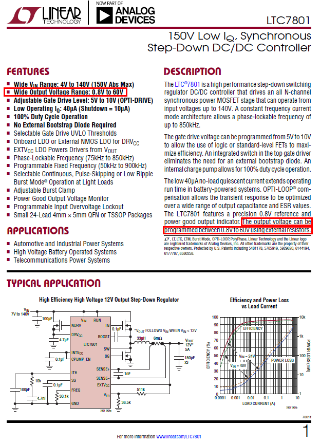
With a sufficient input voltage supply (i.e. 70 volts) you don't need a buck-boost regulator so just consider a buck like this one: -
Getting the output down to 0 volts requires extra circuitry but maybe 0.8 volts is sufficient? Controlling from an MCU would require some external circuitry and possibly consider using a digipot but there are other ways to skin a cat such as injecting a voltage into the VFB pin via a high value resistor from a DAC.
Using the MCU controller and DAC/Digipot means that other pins of the MCU can be used for a serial interface.
-
\$\begingroup\$ you mean I just connect the DAC output to VFB pin? by putting different analog values on VFB pin, we can achieve different output voltages? in this situation, we should use Digipot or not? \$\endgroup\$ Commented Aug 3, 2018 at 13:00
-
1\$\begingroup\$ No, it's not that simple. You set the feedback resistor values up to produce somewhere around 30 volts without any other connection then, you add the DAC output to the VFB pin via a high value resistor of about the same value as the VFB resistor going to ground. If your DAC output is producing 0.8 volts then the output will be 30 volts. If you drive the DAC output to 0 volts then 60 volts will be produced. If you drive the DAC output higher than 0.8 volts, the power supply output drops down from the nominal 30 volts...... \$\endgroup\$– Andy akaCommented Aug 3, 2018 at 13:08
-
1\$\begingroup\$ ..... At 1.6 volts on the DAC output the power supply will be close to producing only 1 volt. It's a little complex to explain but if you have a simulator you should use it to get the general idea. \$\endgroup\$– Andy akaCommented Aug 3, 2018 at 13:08
You do not indicate how much control you want or need or if you have other requirements.
I believe using an off the shelf (OTS) unit would be your best bet unless you want to actually go into production selling these supplies. If they are for internal use I would have someone else do all the hard work. If it is for hobby, test, development or experimental use then I would find a cheap unit and modify it as needed. If you plan to develop I would still purchase half a dozen competitive units and reverse engineer them and read all the data sheets and application notes for parts they use.
There are a number of serial programmable power supplies on the market from US$30 to US$340-55=$285 in the 60V 5A range some with charging programs built in. They are typically needing a filtered input voltage with no dips below the output (+2V or so) and the rest is done in a simple PCB. The more expensive ones include a case and the input supply.
Here is a Open Source hack of a similar 50V 5A switcher that you could start from.
Planning to develop one from scratch is going to cost you mode.
EDIT:
There are even more professional solutions that have software licences inside rack mainframes and all such neat stuff. The prices may also be professional but the products are sure to be of a high quality.

