1
\$\begingroup\$

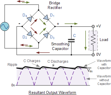
I read some about a full wave rectifier on this website and when it got to the section of smoothing capacitor, and showed this graph and schematics:

enter image description here

It was also said that:

Here the 5uF capacitor is charged to the peak voltage of the output DC pulse, but when it drops from its peak voltage back down to zero volts, the capacitor can not discharge as quickly due to the RC time constant of the circuit.

This got me thinking about the mathematical analysis of this circuit, because I wanted to know what the time constant is. I assume it is not T = RC like in a resistor-capacitor series circuit, but something else.

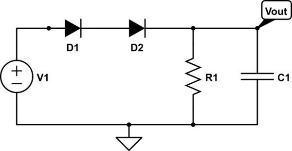
So I assume the circuit can be shown like this now:
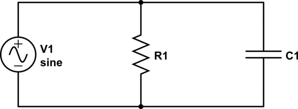
schematic

simulate this circuit – Schematic created using CircuitLab

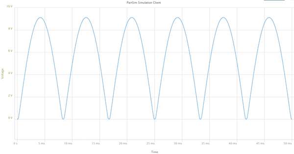
Only now V1 isn't really a sine function but rather this:

enter image description here

I have Googled for a the math here but I couldn't find much, the best thing I found was this, showing how to find the impedance or current in the circuit.

My questions are:

  1. How can I describe the source (V1 in my circuit below), the output of the bridge rectifier, as a mathematical function?

  2. What is the time constant here?

  3. Here is something I'm very confused over. If the voltage is equal in a parallel circuit, aren't the waveforms supposed to be the same? How is the waveform of the voltage on the capacitor different from the one on the source (again, V1 in my circuit).

Thank you.

\$\endgroup\$
4

2 Answers 2

3
\$\begingroup\$

Your circuit can not be described as you think because a true voltage source would maintain the voltage and sink current as well as supplying it.

A better approximation would be.

schematic

simulate this circuit – Schematic created using CircuitLab

This circuit has two diodes since when the bridge rectifier is conducting there are two diode drops.

\$ V_1 = |V_{pk} \cdot \sin(2 \pi f t)|\$ where \$ V_{pk} \$ is the peak voltage of the input AC, \$ \sqrt{2} \cdot V_{rms} \$

The time constant \$ \tau = R_1 \cdot C_1 \$ when the diodes are not conducting. Taking the peak voltage on C1 to be the peak voltage on V1 minus two diode drops and calculating the droop using half the period for the input AC will give you a slightly pessimistic estimate of the output ripple.

You can get a better estimate if you compare the voltage on V1 in more detail but the quick method is usually good enough for design purposes.

\$\endgroup\$
3
  • \$\begingroup\$ Question, if you describe the circuit like this, Wouldn't Vout (assume without capacitor, I'm talking about the diodes) be half the sine wave, with the negative part of the sine wave zero? Meaning, it will be half-a-sine, zero, half-a-sine, zero, half-a-sine, zero.... (half a sine is positive) \$\endgroup\$
    – nettek
    Commented Aug 6, 2018 at 11:37
  • \$\begingroup\$ Also, shouldn't you add two more diodes connected to the negative part of V1, with one of the diode's cathode connected to the negative part of V1 (the opposite of D1 and D2)? \$\endgroup\$
    – nettek
    Commented Aug 6, 2018 at 11:38
  • \$\begingroup\$ There are two diode shown because two diodes are conducting in series D1 and D3 in the positive half cycle, D2 and D4 in the negative one. Circuit reference refer to your original circuit. \$\endgroup\$ Commented Aug 7, 2018 at 7:54
1
\$\begingroup\$

The four diodes make this circuit change paths where current flow during V1's cycle: you can roughly divide its operation into two different modes....

  • one mode where the diodes connect V1 to the RC load

  • the other mode where V1 is disconnected from the RC load.

Viewed this simplified way, diodes operate like switches. When |V1| < Vc, then |V1| is isolated by an open switch. This discontinuous operation means that you cannot apply a voltage source \$ |V1|_{(t)} \$ and use linear circuit analysis to find voltage across C1 and R1 - the diodes make it a non-linear circuit.
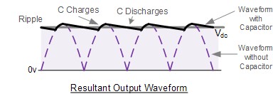
C Charges, C discharges
In this diagram, the two operating modes are described as C Charges and the other C Discharges. The diodes connect V1 to R,C only during the C Charges period.

\$\endgroup\$
2
  • \$\begingroup\$ When you speak of linear circuit analysis, do you also mean using differential equations or a Laplace transform? Because that's what I've been trying to do. \$\endgroup\$
    – nettek
    Commented Aug 5, 2018 at 18:22
  • \$\begingroup\$ @Eran Your assumed equivalent circuit involving only V1sine, R1, C1 and ignoring the diode function will lead you astray. The non-linear action of the diodes radically alters the output voltage waveform and can't be neglected. \$\endgroup\$
    – glen_geek
    Commented Aug 5, 2018 at 19:42

Your Answer

By clicking “Post Your Answer”, you agree to our terms of service and acknowledge you have read our privacy policy.

Not the answer you're looking for? Browse other questions tagged or ask your own question.