0
\$\begingroup\$

I am working on a project to add some digital processing, using Arduino, to an old Electro-Mechanical Pinball Machine. Specifically, I want to detect the score reel triggering on the pinball machine and make a digital version of the score.

When a score reel is triggered, a switch closes, putting power into the coil of the score reel mechanism. This then advances the reel one position, and the power is switched off to the coil.

The pinball uses 25V AC through the switches and the coils. I have connected up and opto-isolator circuit across the switch, and so I can detect when it is powered. If I sample it constantly, of course with it being AC, I get a lot of ON/OFF's per second (UK 50Hz). I have programmed in a delay, which is partially working, but I either get too many or too few digital readings, compared to the mechanical movement of the score reel itself.

Part of the problem is that within the pinball machine, lots of different targets, rollover switches, etc. can trigger a point score. These work at different speeds and switch the coil on for different time periods. Also, say, if the pinball rolls over a rollover switch slowly, that switch is on for a long time, compared to a fast moving ball that triggers the switch for much less time. So, I cannot rely on fixed timing. I need to treat one instance of the switch being truly on as one digital read (or point score).

I have tried a full bridge rectifier, to turn the AC signal into DC, but this doesn't help fully either, although has improved. So I'm looking for any other ideas please.

\$\endgroup\$
1
  • 1
    \$\begingroup\$ The bridge to turn the signal into DC should be the right way to go, then use a capacitor to smooth it and a resistor to discharge it quickly when the AC goes away. What have you got after the bridge at the moment? \$\endgroup\$
    – Finbarr
    Commented Aug 30, 2018 at 8:46

4 Answers 4

1
\$\begingroup\$

I've worked on pinball machines for 15 years, Electro Mechanicals produce all kinds of stray noise when coils energize and De-enegized. You will have to deal with the noise. Below is a simple schematic, the output should be from across the coil not the switch. The size of the capacitor and resistor will have to be determined based on: time on <> verses ripple from the 60 Cycle. I spent many weeks trying to make an electro mechanical slot machine work. It was built by another company but was plagued with errors from switching noise. Got it close but not prefect.

Electronic Pinball Machines have noise diodes, capacitors and resistors.

The schematic editor keeps sending the lead from (C1 to LED) to the rear. It looks fine in editor but not here.

schematic

simulate this circuit – Schematic created using CircuitLab

\$\endgroup\$
0
\$\begingroup\$

Good question. Here's what I would do: First I would build some kind of AC peak detector, and maybe even give it a threshold voltage so that it doesn't detect a "peak" unless it's >15v or something.

Then I would basically try to model the score reel using software. It will probably not be perfect, but it should be able to get pretty close. I would assume that the wheel needs to be energized for X peaks before it "latches". I would also assume that there's a certain reset rate, where if there are no peaks then the solenoid retracts. This assumes the wheel is spring loaded to return to an integer position if it gets a partial trigger. To model that, I would decrement the peak counter at a specific rate over time.

Once you register a trigger, just wait for the peak count to go back down to zero and then reset the whole thing.

Another option would be to attach some kind of encoder to the first disk of the score reel. I think that's more likely to get a perfect count over a long period of time.

\$\endgroup\$
0
\$\begingroup\$

schematic

simulate this circuit – Schematic created using CircuitLab

Figure 1. Relay isolation.

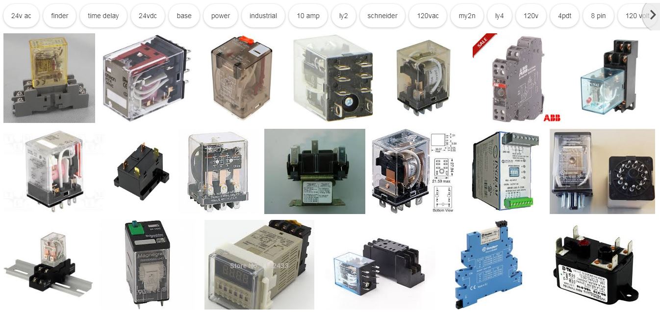
I would first attempt to find a quick-acting 24 V AC relay, wire that in parallel with the reel solenoid and use a debounced contact of the relay to drive the micro-controller GPIO with internal pull-up enabled.

enter image description here

Figure 2. A selection of 24VAC+relays found in an image search.

If your counter reel can react to the shortest pulse then your mechanical relay should be able to as well. I would be inclined to mount the relay close to the micro and run a twisted pair of wires to the coil to minimise any coupling between the AC wiring and the logic signals.

\$\endgroup\$
0
\$\begingroup\$

What you need is to do signal processing. You microprocessor samples the input voltage quite often and will see the 50Hz signal as its input at least sometimes. There are various ways you could "clean" the signal to what you want to achieve.

One simple way is to simply include a low pass filter in the electronic side of things. In another answer you see a simple circuit with a diode + resistor + capacitor doing this. Another way is to use an AC relay, the switching on and off depends on mechanical things moving and hence will do a sort of low pass filtering. You need to get a relay with a correct ballpark switching time -- a really large relay may actually be to slow and not release quick enough for you to see the "off" states.

Alternatively you can do it in software. If you run sampling in a loop in program will have to do some filtering. Basically, a "1" state should stay on until you have seen at least a number of "0" states in a row. This will work if you sample at a rate larger than the Nyquist frequency of the incoming signal, which might mean faster than twice the AC frequency. To be on the safe side I would go with four times faster, say 240 Hz when running 60 Hz AC.

\$\endgroup\$

Your Answer

By clicking “Post Your Answer”, you agree to our terms of service and acknowledge you have read our privacy policy.

Not the answer you're looking for? Browse other questions tagged or ask your own question.