I am working on a interface between an Arduino microprocessor and a old electromechanical pinball machine to track the scoring and light up some LED's based upon that.
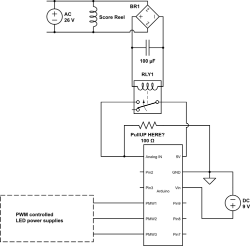
I made a circuit diagram... or I think it might be described as that. I have never done that before and may have more than one tragic mistake.
The pinball machine is the 26V AC coil on the top left, that coil when energized turns a score reel... I am going to tap into the input voltage for that coil and hope to convert to DC, trigger a relay and send a signal to the microprocessor to enable me to "watch" the scoring on the pinball machine with the arduino processor and control some LEDs (shown bottom left). All the circuit stuff (but for the 26 V AC coil) are in a project box.
Question I have, is do I have to worry about filtering (and how would I) the reverse voltage (shut down voltage?) coming off that 26 V AC coil inside the machine. Basically, I am going to run wires from that to a rectifier/smoothing capacitor to trigger a relay (24 V DC relay) and have that switch a 5V DC signal to an Arduino input pin.
I am not sure I need to filter it... will the relay chatter from the reverse voltage? Will it possibly destroy the relay? Kinda new territory. Lets hope my diagram is functional and try to be nice to the new guy... happy to make corrections and listen. Thats what I am here for.
Any other stupid mistakes you can point out would be great. I can also list the exact components I am using if required.


