0
\$\begingroup\$

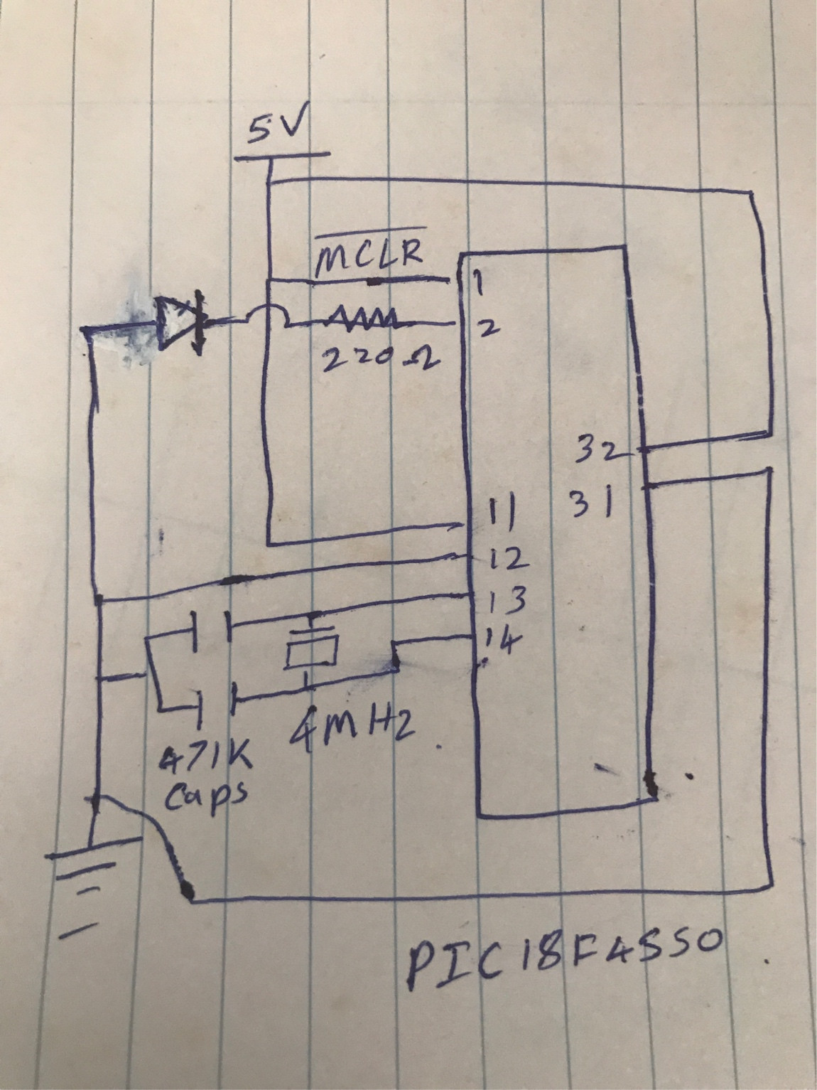
I tried to code LED on-off program for test PIC18F4550 microcontroller. The code can program to IC using Pikkit 2 but a program is not working. I code by using MikroC Pro for Pic 6.6.1. I am using 4Mhz crystal oscillator.

Why program is not working? is it IC not working?

Code:

void main() {
  TRISA.B0=0;

  while(1){
     PORTA.B0=1;
     Delay_ms(2000);
     PORTA.B0=0;
     Delay_ms(2000);
  }

}

This is my circuit diagram:

circuit

\$\endgroup\$
3
  • \$\begingroup\$ I only have small experience with PIC16 but the loading capacitance is way too high and have you set up corresponding PORT register? \$\endgroup\$
    – Long Pham
    Commented Sep 23, 2018 at 7:22
  • \$\begingroup\$ And also, was it a crystal oscillator or crystal resonator? \$\endgroup\$
    – Long Pham
    Commented Sep 23, 2018 at 7:26
  • \$\begingroup\$ Be sure to put a capacitor on your supply voltage! (Close to pin 31/32) \$\endgroup\$
    – Mike
    Commented Sep 24, 2018 at 6:48

2 Answers 2

1
\$\begingroup\$

TRIS are the registers that control the direction (input or output) of a pin. You use only this register, so all you are doing is toggling between input and output.

The first line is correct, but in the loop you must use a PORT or (better) LAT register to toggle the pin between high and low.

\$\endgroup\$
9
  • \$\begingroup\$ Sorry for that that is typing mistake \$\endgroup\$
    – Ind
    Commented Sep 23, 2018 at 7:26
  • \$\begingroup\$ When I use PIC16F887 microcontroller it is working by changing IC modal. \$\endgroup\$
    – Ind
    Commented Sep 23, 2018 at 7:29
  • \$\begingroup\$ What is IC modal?? \$\endgroup\$ Commented Sep 23, 2018 at 7:36
  • \$\begingroup\$ I mean the same code and change IC modal to PIC16F887 IC. I use PIC16F887 microcontroller it is working fine. Why this code not working for PIC18F4550 IC. \$\endgroup\$
    – Ind
    Commented Sep 23, 2018 at 7:38
  • \$\begingroup\$ I think this PIC18F4550 IC is not working. Why it can program? \$\endgroup\$
    – Ind
    Commented Sep 23, 2018 at 7:41
1
\$\begingroup\$

schematic

simulate this circuit – Schematic created using CircuitLab

Figure 1. LED orientations that work.

If the diode in your schematic is the LED in question then it is missing the "light" arrows from the symbol and it is in backwards so it will never light.

schematic

simulate this circuit

Figure 2. This RC addition causes the \$ \overline {\text {MCLR}} \$ line to follow the power supply with a 10k x 100n = 1 ms time delay.

Also the \$ \overline {\text {MCLR}} \$ may need to be pulled high a little later after the chip has powered up. A small RC time delay is normally used for this. Check the datasheet examples for recommended values. The delay allows the internal voltages to settle and holding the line low resets everything to known initial conditions ensuring proper initialisation.

\$\endgroup\$
4
  • \$\begingroup\$ When I am using PIC16F887A ic it does not have any problem same circuit only changed IC \$\endgroup\$
    – Ind
    Commented Sep 23, 2018 at 9:19
  • 1
    \$\begingroup\$ OK. You might be lucky with the MLCR on the other chip so check the datasheet for this one. The LED cannot work the way you have drawn it. \$\endgroup\$
    – Transistor
    Commented Sep 23, 2018 at 9:22
  • 1
    \$\begingroup\$ I removed capacitors of oscilators then it is working why is that? \$\endgroup\$
    – Ind
    Commented Sep 23, 2018 at 10:41
  • 3
    \$\begingroup\$ Capacitors were too large. There is sufficient stray capacitance for the oscillator to work. \$\endgroup\$ Commented Sep 23, 2018 at 11:44

Your Answer

By clicking “Post Your Answer”, you agree to our terms of service and acknowledge you have read our privacy policy.

Not the answer you're looking for? Browse other questions tagged or ask your own question.