0
\$\begingroup\$

I want to recreate a project found at this link where an optocoupler's LED is a driven by the receiver output of a MAX485.

Now, my question is, the LED series resistor (R5) value is 470ohms, if my calculation is right the led is taking around 10.6mA however I cant find in MAX485's datasheet, about how much can RO pin sink. The most I got is Vol where it says Io max is 4mA. Does that mean it can only sink 4mA? In that case, how is that shield working? because 6N137 needs at least 5mA to turn ON.

\$\endgroup\$
3
  • \$\begingroup\$ Interestingly a receiver output short-circuit current is specified, but while there's explicit mention of short circuit protection for the driver output, it does not explicitly say that this is implemented for the receiver output. \$\endgroup\$ Commented Sep 23, 2018 at 16:56
  • \$\begingroup\$ @ChrisStratton The receiver output is an internal logic signal so you wouldn't expect any more protection than any logic IC has. The outputs are exposed to the end user who can easily short them. \$\endgroup\$ Commented Sep 23, 2018 at 17:00
  • \$\begingroup\$ @SpehroPefhany - seeing a short-circuit current rating on an "internal" logic output, while not unheard of, is not usual. More typically there is a maximum source or sink current spec, but not here. So my point is that the data sheet implies a different situation than with common logic, but it does not explicitly state different rules. In effect, the really meaningful question is what can be safely be inferred. \$\endgroup\$ Commented Sep 23, 2018 at 17:02

3 Answers 3

1
\$\begingroup\$

The datasheet does not tell you the maximum current is 4mA, it tells you that AT 4mA the maximum voltage drop is 400mV (low) over the full temperature range.

The voltage drop is only guaranteed to be less than 1.5V (or maybe 1.25V depending on whether they include Vcc tolerance) when driving high, but the design is not using it in that mode.

Chances are good it will be okay at at 6-8mA since the Vds drop is most likely well under the threshold voltage of the MOSFETs where the I-V curve flattens, but it's not explicitly guaranteed.

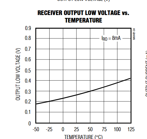
You can see the typical (ie. not guaranteed) receiver output voltage at 8mA here:
enter image description here

So it's about 0.42V at 8mA/125°C. That means it would be about 0.21 typically at 4mA and they've allowed a bit less than 2:1 margin for variations. If we assume a 0.8V drop at 125°C then your current would be about 6.4mA nominally. The opto is only good to 100°C so we have even more margin.

Generally you should check the opto data carefully to make sure you allow enough forward current for all temperature and unit-to-unit variations and also to allow for aging of the LED (which is accelerated at high temperature).

\$\endgroup\$
4
  • \$\begingroup\$ aging of led ? optocoupler stops working after too much use ? also where is Vds ? \$\endgroup\$
    – J. Doe
    Commented Sep 24, 2018 at 3:20
  • \$\begingroup\$ @J.Doe The LED will require more current to emit the same amount of light as it ages. Vds is across the internal N-channel MOSFET at the driver output (drain to source, of course). \$\endgroup\$ Commented Sep 24, 2018 at 3:24
  • \$\begingroup\$ so its better to use a buffer that can sink more current, like 20mA, that will also help after led has aged, correct ? \$\endgroup\$
    – J. Doe
    Commented Sep 24, 2018 at 3:31
  • \$\begingroup\$ @J.Doe Definitely more conservative. It depends on your requirements. Your nominal LED design current is a trade-off of course. Either too high or too low is bad. For hobby purposes I think the published circuit is probably okay. If I was making 1000+ I would look more closely. \$\endgroup\$ Commented Sep 24, 2018 at 10:33
1
\$\begingroup\$

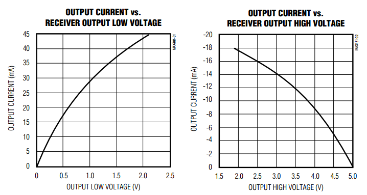
The RO pin characteristics are shown on page 5 of the datasheet: enter image description here

The datasheet does not give an absolute maximum Iout rating for RO, but the graphs imply that it can sink up to 45mA and source up to 18mA, but the output impedance is significant, which means that it the output voltage will pull away from the rail as the output is loaded down.

\$\endgroup\$
0
\$\begingroup\$

If you look at the equivalent driver ESR = RdsOn for Vol/ Iol at any current and supply voltage and temperature, you can include this in the required series R to define the IR diode current limit. Then consider the VI=Pd dissipation which may be small even at 20mA. Typically 5V logic is 50 ohm nominal +/-25%

Vol levels then do not matter as you are not looking for logic output levels but rather photodiode current levels.

This applies to all drivers, 3.3V logic max tends to be 25 Ohms with the same design/process tolerances of 25% or so.

\$\endgroup\$

Your Answer

By clicking “Post Your Answer”, you agree to our terms of service and acknowledge you have read our privacy policy.

Not the answer you're looking for? Browse other questions tagged or ask your own question.