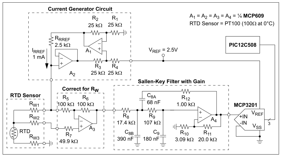
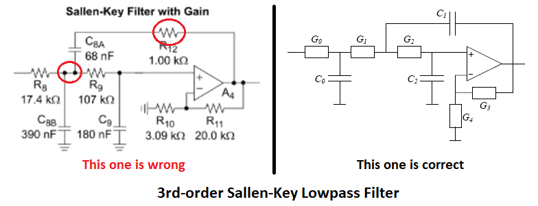
Your linked application note actually tells quite thoroughly the ideas behind the filter, but it's unfortunately engineer's speak to another engineer.
You can simulate the filter. It is at the same time a lowpass filter and an amplifier. The filtering is needed to attenuate all noise that the probe collects from disturbing fields. The component values are selected surely to provide enough attenuation at the most harmful frequencies 50...60Hz and simply to have values that are available. One needs accurate enough resistors, especially R10 and R11 must be ok because they affect the scaling.
3rd degree filter also needs more accurate component values than simpler filters. Bad filter, which attenuates enough at 50 Hz and up, can cause too long fluctuating output or too slow rise to the right voltage when the temperature changes rapidly (=for example the probe has been put to cold or hot liquid). It surely is a design criteria to get the filtered signal to settle fast enough without too much overshoot.
A part of the needed filtering and the calibration can be made in PIC software. To keep the calibration and programmed filtering valid the component values must stay stable.
ADD: The later discussion in comments reveal that you are sensing outdoor air temperature. A simple RC filter surely is enough, because that application can well stand for ex. 15 seconds long settling time.


