1
\$\begingroup\$

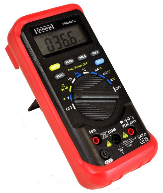
So I got a TekPower TP4000ZC MultiMeter.

Photo of multimeter

(Image source)

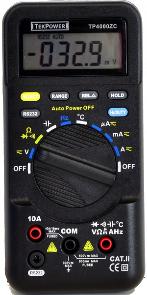
It has COM port and two red ports:

  • V-Ohm-etc. set at 600V Max and 500mA Max Fused
  • 10A red fused port.

Unlike other multimeters, there are no separate red ports for Volts and Amps. TP4000ZC MultiMeter has literally the inscription between COM and 1st red port, saying that using them is 600V MAX and 500mA max.

I want to measure voltage in the wall socket.

I presume that plugging probes into the outlet would complete the circuit, thus making the multimeter as the load of some sort.

Since my first red port has 500mA MAX, I presume that wall outlet has more amperage flowing than pathetic 500mA. (Arent they set at 15A?)

So I plug the red cable to 10A red port, black to COM. Black probe goes into larger opening, red probe into the smaller opening of the outlet, set the multimeter knob to Volt setting

AND ..... SPARK! (in the outlet)

So I disassembled the multimeter and saw that the 10A fuse connects COM and 10A Red port.

I guess I shouldn't have put red cable into 10A port, but kept it in 500mA red port V-Ohm-Amp-Hz one.

My questions:

  1. Why the 1st red port (600 V / 500mA MAX red port V-Ohm-Amp-Hz one) is the correct one to use when measuring voltage in the outlet?

  2. Wouldn't plugging the multimeter into the outlet complete the circuit, allowing current (under voltage potential) to flow into the multimeter (regardless of whether the multimeter is plugged in in series or in parallel)?

  3. Thus I should have "honored" the 500mA MAX warning (or 250mA on some other multimeters) on the 1st red port and theoretically plugged into 10A port?

  4. If the fuse that connects 2nd red port (10A) was set at 10A (F10AL250V), then could I presume that the multimeter just became a "load" in the circuit - e.g. just like any small appliance - then why fuse broke, why it did not act as said "load"?

Thank you in advance for your time typing the answers for this. I cannot find clear answers to this despite plethora of resources that just goes around my questions tangently.

\$\endgroup\$
6
  • \$\begingroup\$ you were measuring the short circuit current that an electrical outlet can deliver and you blew the internal fuse ..... use the other red port for voltage .... the 500mA warning is for current measurement (dial set for current) \$\endgroup\$
    – jsotola
    Commented Oct 31, 2018 at 21:46
  • 3
    \$\begingroup\$ you googled the wrong thing .... google how to use a dvm \$\endgroup\$
    – jsotola
    Commented Oct 31, 2018 at 21:46
  • 1
    \$\begingroup\$ I guess a user manual would help as well \$\endgroup\$
    – Eugene Sh.
    Commented Oct 31, 2018 at 21:47
  • 1
    \$\begingroup\$ The 10A plug is only to be used for current measurements. \$\endgroup\$
    – Hearth
    Commented Oct 31, 2018 at 21:50
  • \$\begingroup\$ Noted. Thank you for your time and clarification. The manual and various videos I watched never touched the phrase on the MM I have "500mA MAX" on V-Ohm-A port- it just confused me and let me to overthink \$\endgroup\$
    – Eksel
    Commented Oct 31, 2018 at 22:24

4 Answers 4

2
\$\begingroup\$

Page 16 of your manual:

2.2 DC and AC Voltage measurement

1) Connect the black test lead to "COM" socket and red test leads to the "VΩHz" socket.

2) Set the selector switch to desired “ V [squiggle]” position, and press “SELECT” key to choose function.(DC or AC)

3) Connect the probes across the source or load under test.

\$\endgroup\$
1
  • 1
    \$\begingroup\$ Manual does indeed state this:) The phrase "500mA MAX" on the body of MM became faulty instruction manual "override" in my head. I just could not presume 500mA and outlet in the same context. Thank you for your time \$\endgroup\$
    – Eksel
    Commented Oct 31, 2018 at 22:51
2
\$\begingroup\$

Why the 1st red port (600 V / 500mA MAX red port V-Ohm-Amp-Hz one) is the correct one to use when measuring voltage in the outlet?

Presumably you wanted to measure voltage so the V and COM sockets are correct but you need to select V AC range to measure it.

Wouldn't plugging MM into the outlet complete the circuit, allowing current (under voltage potential) to flow into MM (regardless whether MM is plugged in in series or in parallel).

Current measurement is done by measuring the voltage drop (usually about 200 to 300 mV) across the very low value shunt resistor in the meter when switched to amps range. By shorting out the mains with your meter on current range you would have allowed a current of > 100 A to flow until the fuse blew. This was very dangerous.

Thus I should have "honored" the 500mA MAX warning (or 250mA on some other MM) on the 1st red port and theoretically plugged into 10A port?

The 10 A port has a much lower shunt resistance value than the mA port and the fault current could have been much higher and more dangerous.

If the fuse that connects 2nd red port (10A) was set at 10A (F10AL250V), then could I presume that MM just became a "load" in the circuit - e.g. just like any small appliance - then why fuse broke, why it did not act as said "load"?

Current measurements are done with the meter in series with a real load. The load limits the current to a sensible value that the meter can handle.


You have been very fortunate not to have been injured. You need to learn a lot more before playing with mains power.

Never connect an ammeter directly across a non-current limited supply.

\$\endgroup\$
1
  • \$\begingroup\$ Thank you, Transistor, for the answering all my questions individually. I will need to take yours, Phil and Selvek answers to "digest" more. Especially, your phrase - "The load limits the current to a sensible value that the meter can handle." That what I was vague and confused about. \$\endgroup\$
    – Eksel
    Commented Oct 31, 2018 at 22:39
2
\$\begingroup\$

Notice how the right side red port has a bunch of symbols over it, which correspond to the symbols on the dial. The key is that every one of those measurements uses that port - notice both voltage and current are included.

Your multimeter is smart - it knows that voltage measurements can only be taken with high input impedance, and current measurements can only be taken with low input impedance. Thus, when you select voltage on the dial, the multimeter has a high input impedance (probably megaohms). So when you connect it to a 120V outlet, virtually no current flows.

When you set the dial to uA or mA, the multimeter switches itself to low input impedance. If you were to connect it to the outlet with this setting... bzzt!

On the other hand, the 10A port is only used for current measurements, so it always has a low input impedance! If you connect it to the outlet, you'll short circuit the outlet - as you found out.

If you're curious, you can use a second multimeter to directly measure the input impedance and see how it changes as you change the multimeter settings.

D:\Misc\PicsToUpload

\$\endgroup\$
1
  • \$\begingroup\$ Thank you, so much, Selvek - I think you and Phil are the closest ones to understanding on what I got me confused. "....Thus, when you select voltage on the dial, the multimeter has a high input impedance (probably megaohms). So when you connect it to a 120V outlet, virtually no current flows...." - this clarifies my confusion! \$\endgroup\$
    – Eksel
    Commented Oct 31, 2018 at 22:56
1
\$\begingroup\$

The 10A circuit has its own socket so that the current doesn't have to go through the selector switch - the selector does have a contact that switches the mode so that the brains in the meter knows to look at the voltage developed across the 10A shunt. All the other ranges go through the one V-Ohm-Amp-Hz socket, and then through the selector to connect to the appropriate circuit in the meter, the mA and Ua circuits will connect to lower rated shunts - this is where the 500mA warning is needed, to prevent putting too much current through that circuit. Often there's a second fuse that protects the mA range input.

The voltage ranges connect to dividers inside the meter that scale the voltage to the value that the meter itself reads, often 200mV. The divider has a fairly high resistance, often in the megohms, so that the current drawn when measuring voltage is very low. The current capacity of the circuit you're measuring is irrelevant.

\$\endgroup\$
1
  • \$\begingroup\$ Thank you, so much, Phil - I think you and Selvek are the closest ones to understanding on what I got me confused. Most important sentence for me here: “ …. this is where the 500mA warning is needed, to prevent putting too much current through that circuit.” - Not understanding this nuance got me confused. \$\endgroup\$
    – Eksel
    Commented Oct 31, 2018 at 23:00

Your Answer

By clicking “Post Your Answer”, you agree to our terms of service and acknowledge you have read our privacy policy.

Not the answer you're looking for? Browse other questions tagged or ask your own question.