1
\$\begingroup\$

enter image description here

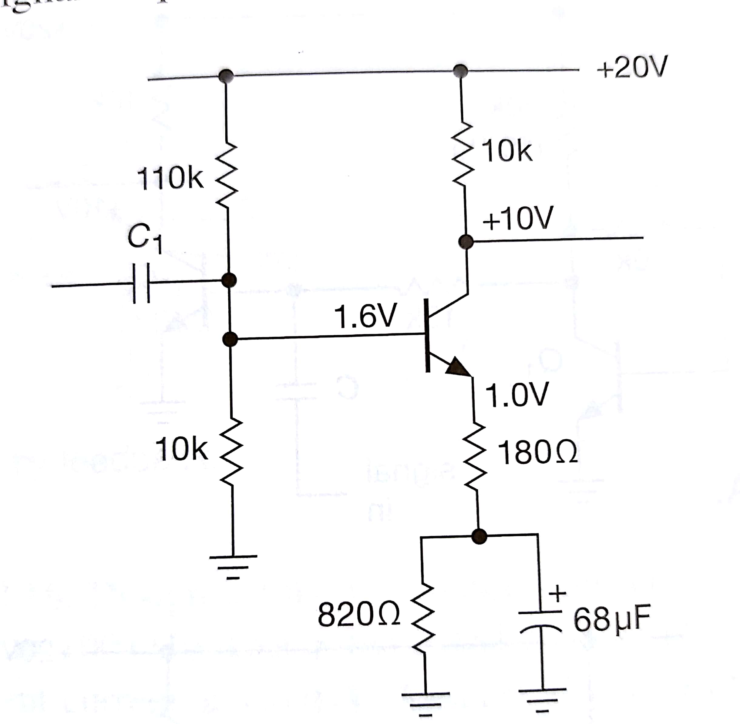
This is an amplifier which has voltage gain of 50, quiescent current 1 mA and the input is signals from 20 Hz to 20 kHz. I calculated the collector current which is 1 mA, using that I calculated emitter resistor value which is 1 kohms. Now how did he decide the resistor values of emmiter as 180 ohm and 820 ohm when emitter resistance is 1 kohm?

\$\endgroup\$
1
  • 1
    \$\begingroup\$ \$\frac{R_C=10\:\text{k}\Omega}{A_V=50}-\frac{k\:T}{q\:I_C}\approx 174 \:\Omega\$. Rounding up, they got \$180\:\Omega\$. \$\endgroup\$
    – jonk
    Commented Nov 14, 2018 at 7:58

2 Answers 2

3
\$\begingroup\$

What is the purpose of an emitter resistor?

Answer: Stabilizing the DC bias point against uncertainties, tolerances and temperature changes.

What is the consequence? Reduction in gain (negative feedback effect). However, also the (lower) gain value is stabilized against uncertain transistor parameters and the input-output relation is linearized.

In many cases, we want to achieve a trade-off between stabilization and gain reduction. For this purpose, we realize a good (strong) DC feedback (1kOhm) and a somewhat reduced signal feedback because it is only the 180 Ohm resistor that provides signal feedback (820 Ohm are shorted for signals above the corresponding cutoff frequency using a large emitter capacitor).

Edit/Update: Gain formulas:

Rc=10k; RE1=180=hm; RE2=820Ohm; RE=RE1+RE2

(a) DC and AC (far below the cutoff freqency fc):

G=gmRc/(1+gmRE) with transconductance gm=IC/Vt (Vt=26mv).

(b) For AC (far above fc):

G=gmRc/(1+gmRE1)>>>>>>for RE1>>1/gm=26 Ohm we have app. G~Rc/RE1.

(c) Cutoff frequency: fc=1/(6.28*T) with T=CE*[RE2||(RE1+1/gm)]
\$\endgroup\$
1
\$\begingroup\$

In addition to LvW's excellent answer, it's also worth to mention about symmetrical clipping here.

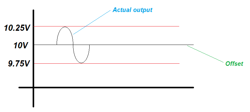
As you might know, the output signal has a DC offset because the output is taken from collector. And the DC offset is the collector voltage which can be calculated easily from DC analysis:

  • Since the collector's quiescent (bias) current, \$I_{CQ}\$, is 1mA, collector voltage will be \$V_C = VCC - I_{CQ} \cdot R_C = 20-1mA\cdot 10k = 10V\$

So, the output signal (AC) swings around 10V. For example, if the input is 10mVpp and gain is 50 then you can easily say that the output will be 500mVpp. But since the output is taken from collector, it will swing between 9.75V and 10.25V:

enter image description here

If the input is high enough (e.g. 200mVpp min.) then the output signal will swing between 0V and 20V; and, of course, it will be symmetrically clipped.

Probably that's why the collector resistor is chosen as 10k.

Now, the designer decided the bias current to be 1mA and the gain to be 50. And also (s)he whats the DC offset to be 20/2=10V due to the need (?) of symmetrical clipping. The next task is to determine the active-in-AC emitter resistor. It should be 10k/50 = 200R. So, (s)he says "Hmm, I've 1k as active-in-DC emitter resistor but now I need 200R. So I should bypass a 800R portion with a sufficiently large capacitor." That's why 820 is bypassed with a 68uF capacitor (by the way, 800R is not an easy-to-find value, but 820R is a standard value).

\$\endgroup\$
2
  • \$\begingroup\$ Pardon me but what is active-in-ac emitter resistor? \$\endgroup\$
    – user204304
    Commented Nov 15, 2018 at 5:49
  • \$\begingroup\$ Sorry, it's not an electrical convention. In DC analysis, capacitors are taken as open. And in AC analysis, capacitors are taken as shorted. So, in DC analysis of your circuit, emitter resistor is 820R + 180R = 1k. And in AC analysis, 820R resistor is shorted by 68uF capacitor. Thus, I named total remaining emitter resistor as "active-in-ac emitter resistor". And it's 180R. \$\endgroup\$ Commented Nov 15, 2018 at 9:45

Your Answer

By clicking “Post Your Answer”, you agree to our terms of service and acknowledge you have read our privacy policy.