1
\$\begingroup\$

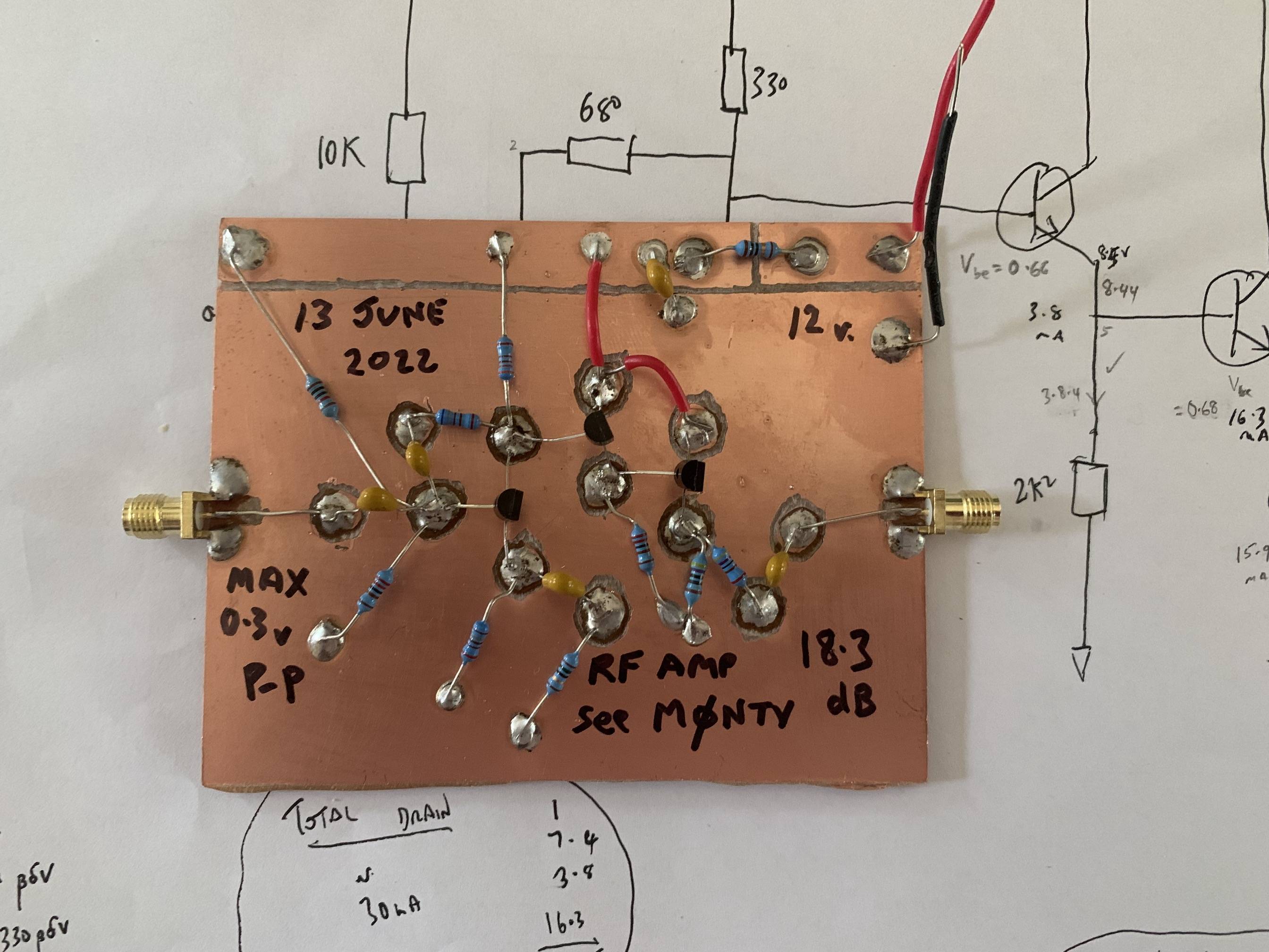
I made this 3 transistor Rf amp which works well at 10 MHz and has 50 ohm output impedance, a gain of 8.2 (18.3 dB) and quiescent curent of 28.6 mA. It consists of a common emitter stage followed by 2 emitter follower stages. (Credit: Nick the vic M0NTV)

Rf amp photo

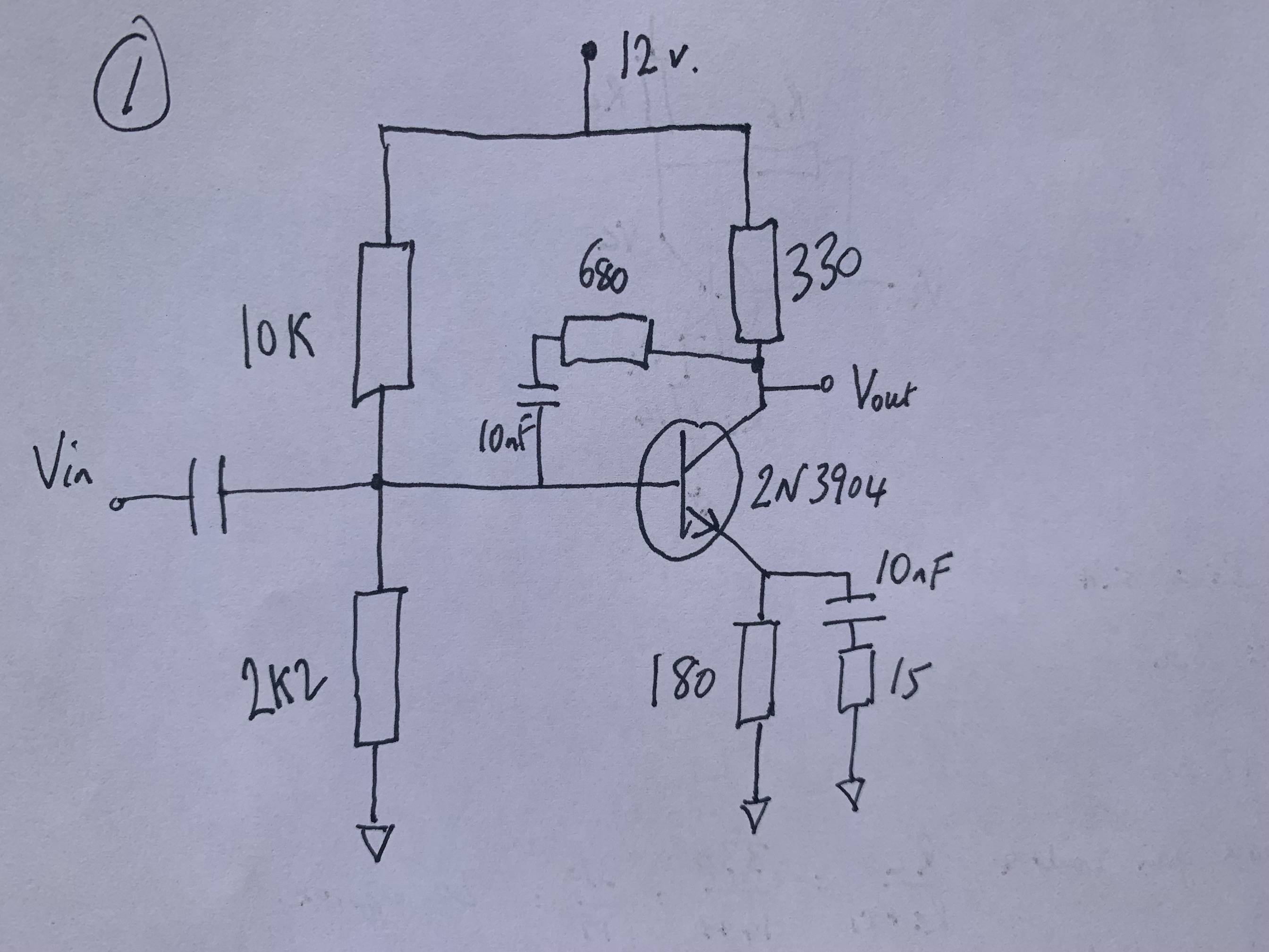
My question concerns only the first stage and, in particular the 680 Ohm feedback shunt resistor between collector and base.

Diagram 1

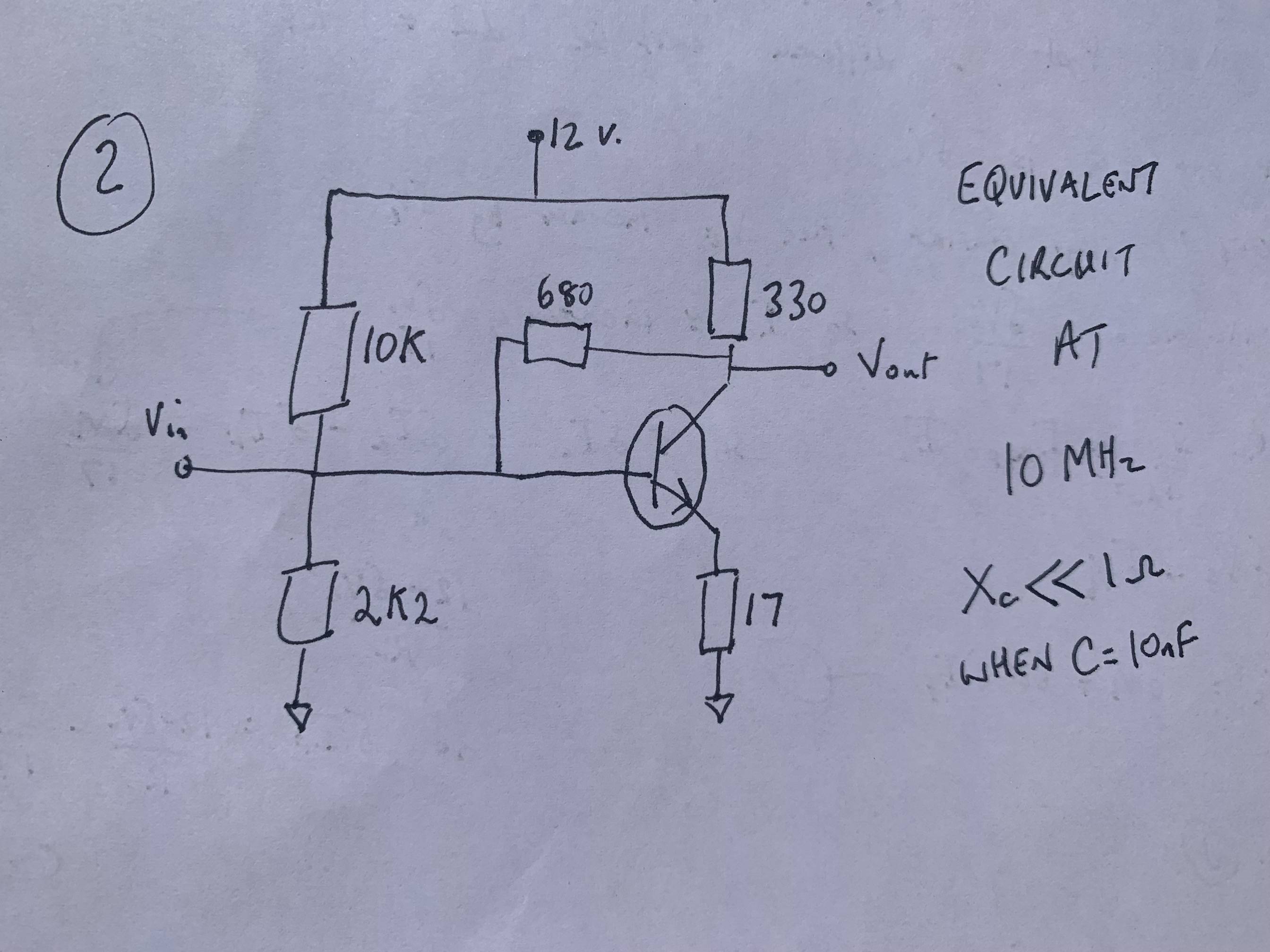
At 10 MHz the reactance of a 10 nF capacitor is <<1 Ohm so, as far as the signal is concerned, all capacitors can be replaced by a short. This results in having 2 emitter resistors in parallel (180 & 15) which make us 14 Ohms together. To this I have added the internal emitter resistance of re = 3 Ohms (25 mV divided by the 8 mA emitter current). This gives the simplified circuit:

Photo 2

If I'm correct, but for the feedback resistor the gain would be approx 330/17 i.e. 19.4 or 25.9 dB (Rl divided by RE total). So the effect of introducing the feedback resistor is to halve the gain.

I've tried doing the calculation considering the effect of a small dV increase in Vb to work out the gain Av = dVc/dVb but end up going round in circles. Going to LTSpice might give the answer but would add nothing to my understanding.

Can someone help me out?

\$\endgroup\$

1 Answer 1

2
\$\begingroup\$

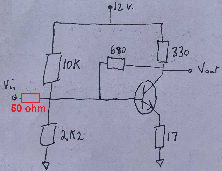
You need to take the source impedance into account to calculate this correctly. I'm assuming that the input source is meant to have a 50 Ω impedance. Hence I'd visualize it like this: -

enter image description here

I'd then analyse it like an amplifier with an open-loop gain of \$\frac{-330}{17}\$: -

schematic

simulate this circuit – Schematic created using CircuitLab

If I call the output Y and the input X, the signal after the summing node (Z) is: -

$$Z = X + Y\cdot\dfrac{50}{680}$$

Then we know that Z multiplied by -330/17 = Y: -

$$Y = \left(X + Y\cdot\dfrac{50}{680}\right)\cdot\dfrac{-330}{17}$$

Hence: -

$$Y\left(1 + \dfrac{16500}{11560}\right) = X\cdot\dfrac{-330}{17}$$

Or,

$$Y = X\cdot\dfrac{-19.412}{\left(1 + \dfrac{16500}{11560}\right)}$$

Can someone help me out?

Chew on it a tad more and the gain (Y/X) comes out at -7.997.

\$\endgroup\$
2
  • 1
    \$\begingroup\$ Oh I get it. The 680 Ohm feedback resistor and the input impedance form a voltage divider (ignoring the biasing resistors which are too high to affect the calculation). Thanks! \$\endgroup\$
    – Dabbo
    Commented Jun 15, 2022 at 10:02
  • 1
    \$\begingroup\$ @user299022 precisely. But, remember that with any single BJT circuit, it can all be a bit hit and miss. \$\endgroup\$
    – Andy aka
    Commented Jun 15, 2022 at 10:04

Your Answer

By clicking “Post Your Answer”, you agree to our terms of service and acknowledge you have read our privacy policy.

Not the answer you're looking for? Browse other questions tagged or ask your own question.