0
\$\begingroup\$

I have only just started to play with electronics (literally less than a week ago) and have purchased myself some cheap Arduino Nano clones, as well as some LEDs, resistors (only 10 ohms at the moment, but more varieties are coming), a breadboard and some jumper cables.

The reason I've got into this is that I also make scale models and want to light them up with LEDs and fibre optics. I may play with Bluetooth connectivity etc as a later date, but first, my issue with multiple LEDs and their power requirements.

Please excuse and correct me if any of this is wrong, its all based on my current (and probably incorrect) understanding at this point...

The Arduino Nano has 15 digital I/O pins and 6 of them use PWM. These pins output 5 V at a maximum of 40 mA (20 mA is recommended).

I want to run 4 LEDs from one of these pins. The LEDs I have are 3.3 V and 20 mA.

This means that I'll either not be able to light them (9.9 V / 20 mA if I run the LED's in series) or I'll damage the Arduino if I run them in parallel (3.3 V at 60 mA).

I came across a video (Here's the link) that discussed this issue, and suggested the use of a transistor to get around it, and the video makes sense, but it never mentioned how to make sure I get the correct transistor for my project.

Is there a simple way to calculate which transistor I want/need? For instance in my case, I have 4 LEDs, each one needs 3.3 V and 20 mA. What should I look for in a transistor to handle this, and how do I calculate it for myself?

\$\endgroup\$
2
  • \$\begingroup\$ You cannot "calculate a transistor." You can calculate some of the things you need to know (like expected current.) Other things are given (like operating voltage.) From the things you can calculate and the things that are given, you go looking for a transistor that will meet the requirements you have put together. There is no equation into which you can put requirements and calculate a part number. \$\endgroup\$
    – JRE
    Commented Nov 19, 2018 at 11:51
  • \$\begingroup\$ @JRE the "calculating the necessary transistor" is my wording, not Karl's. Sorry. \$\endgroup\$ Commented Nov 19, 2018 at 11:54

2 Answers 2

1
\$\begingroup\$

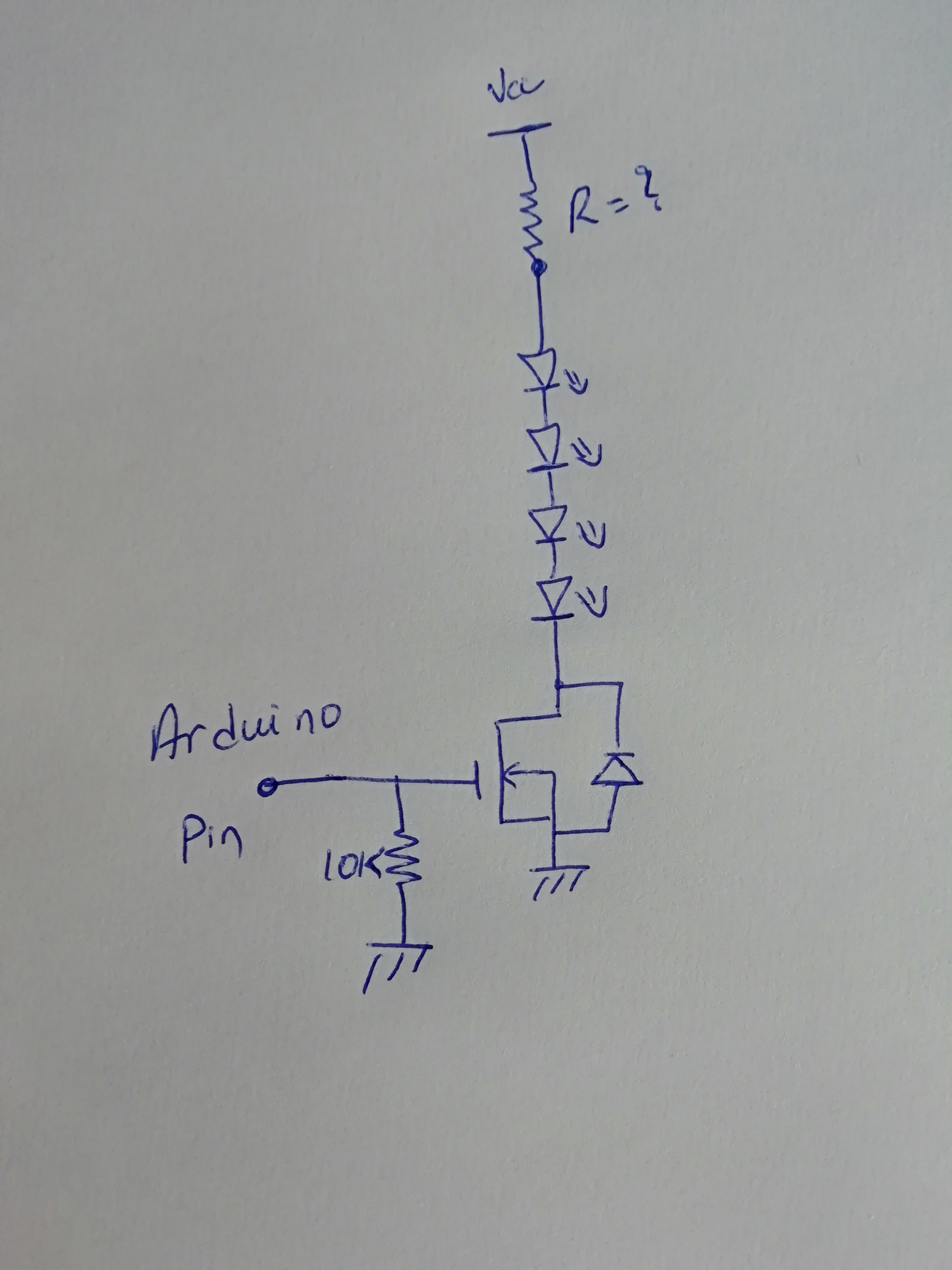
Start with a type of transistor, for your application a N chanel Mosfet is the best to use

To chose a transistor you have to define some parameters like

Vth : in your case you have to chose one around 1 - 3 volt (to be sure that the Arduino 5V will be enogh to sature it)

Vgsmax : you will use Arduino to have margin, take a transistor with at least 8V

Rdson : Not critical in your case (just to minimise loses take the one with the minimum Rdson)

Id : the current in your circuit, in your case it is 20mA so you have to chose one with support a greater current (attention do not take the value in the first page, generally it is given for a specific Vgs and Vds, verifyyour condition, or go and find this value in the abacus The schématic you can do)

\$\endgroup\$
6
  • \$\begingroup\$ Thanks for your answer Juba. Just so I understand correctly, I wanted to check some numbers relative to my issue and your solution. Vcc: Would this be the voltage from the battery (or power source) used to light the LEDs? If I used a standard 9v battery through a 7805 5v volt power regulator, how do I calculate the resistor that follows the Vcc? Vth: Would be the voltage used to turn on the Transistor? What do you mean "sature it"? VgsMax: I dont understand this at all. Why did you pick a 10k resistor near the bottom of your diagram? \$\endgroup\$
    – Karl
    Commented Nov 19, 2018 at 13:47
  • \$\begingroup\$ First, Vcc is the voltage from your battery. But, if you have 4 LEDs in series and each needs 3.3V you need at least 13.2V. to calculate the resistor that fellows the Vcc you use this formula R=(Ve-Vled)/Iled; where Ve is your source voltage, Vled is the total voltage of the LEDs and Ileds the current through thed LEDs, \$\endgroup\$
    – Juba
    Commented Nov 19, 2018 at 14:34
  • \$\begingroup\$ The voltage that is used to turn on the transistor is the Arduino output, the 10k resistor is called pull-down resistor it is connected to GND, it is used to force a 0V at the gate of the transistor when there no output from the arduino (when to trasfer a new code for exemple) \$\endgroup\$
    – Juba
    Commented Nov 19, 2018 at 14:42
  • \$\begingroup\$ What i mean "sature it" sorry it is a problem of translation, a N MOS need a certain voltage difference between the gate and the source, you have to impose some voltage greater than the Vth to be sure that NMOS is turned on (I don't know if it is clear now ?) \$\endgroup\$
    – Juba
    Commented Nov 19, 2018 at 14:45
  • \$\begingroup\$ Hey Juba, I think I understand a bit more, thank you. Is "lled" the combined current of all the LEDs or just one (or the highest if they're different?) If I have 4 LEDs and each is 20mA, is lled 20mA or 80mA? \$\endgroup\$
    – Karl
    Commented Nov 20, 2018 at 8:16
-1
\$\begingroup\$

schematic

simulate this circuit – Schematic created using CircuitLab

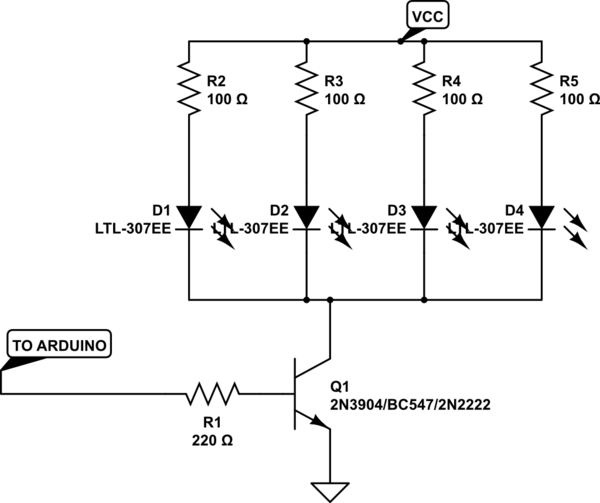
You just need a transistor circuit. you need a PBNO (push button normally open) configuration. so select a NPN transistor

some common part numbers are BC547, 2N2222,

The maximum current of your leds load should be less that Ic (collector current) of transistor.

the maximum volatge should not exceed transistor collector-emitter voltage.

base current to turn on.

frequency response of transistor

\$\endgroup\$
3
  • \$\begingroup\$ This neglects information on how to choose which transistor to use, the influence of the Collector-Emitter diode forward voltage on the series resistor, and it shows the bad practice of having one series resistor for multiple LEDs, so: no. \$\endgroup\$ Commented Nov 19, 2018 at 11:56
  • \$\begingroup\$ Can you please explain in detail, what will be the problems of using One series resistor for few no of leds... \$\endgroup\$
    – Electron
    Commented Nov 19, 2018 at 12:05
  • \$\begingroup\$ The issue is that all fwd voltage of the LEDs are slightly different, and since the current dependency is exponential, you end up with the led with the lowest fwd voltage carrying most of the current. Its life is shortened, then it goes pop, and if it fails open the other LEDs will shortly (seconds) follow. \$\endgroup\$ Commented Nov 19, 2018 at 12:19

Your Answer

By clicking “Post Your Answer”, you agree to our terms of service and acknowledge you have read our privacy policy.

Not the answer you're looking for? Browse other questions tagged or ask your own question.