1
\$\begingroup\$

I read discussions about only using N-channel MOSFETS in h-bridge circuits. I often see things like optoisolators listed. Example: driving high-side N-channel MOSFETs in H-Bridge

But why can't I just use a common transistor like 2N3904 to control extra voltage to my high-side N-channel MOSFET? Please excuse my crude drawing: enter image description here
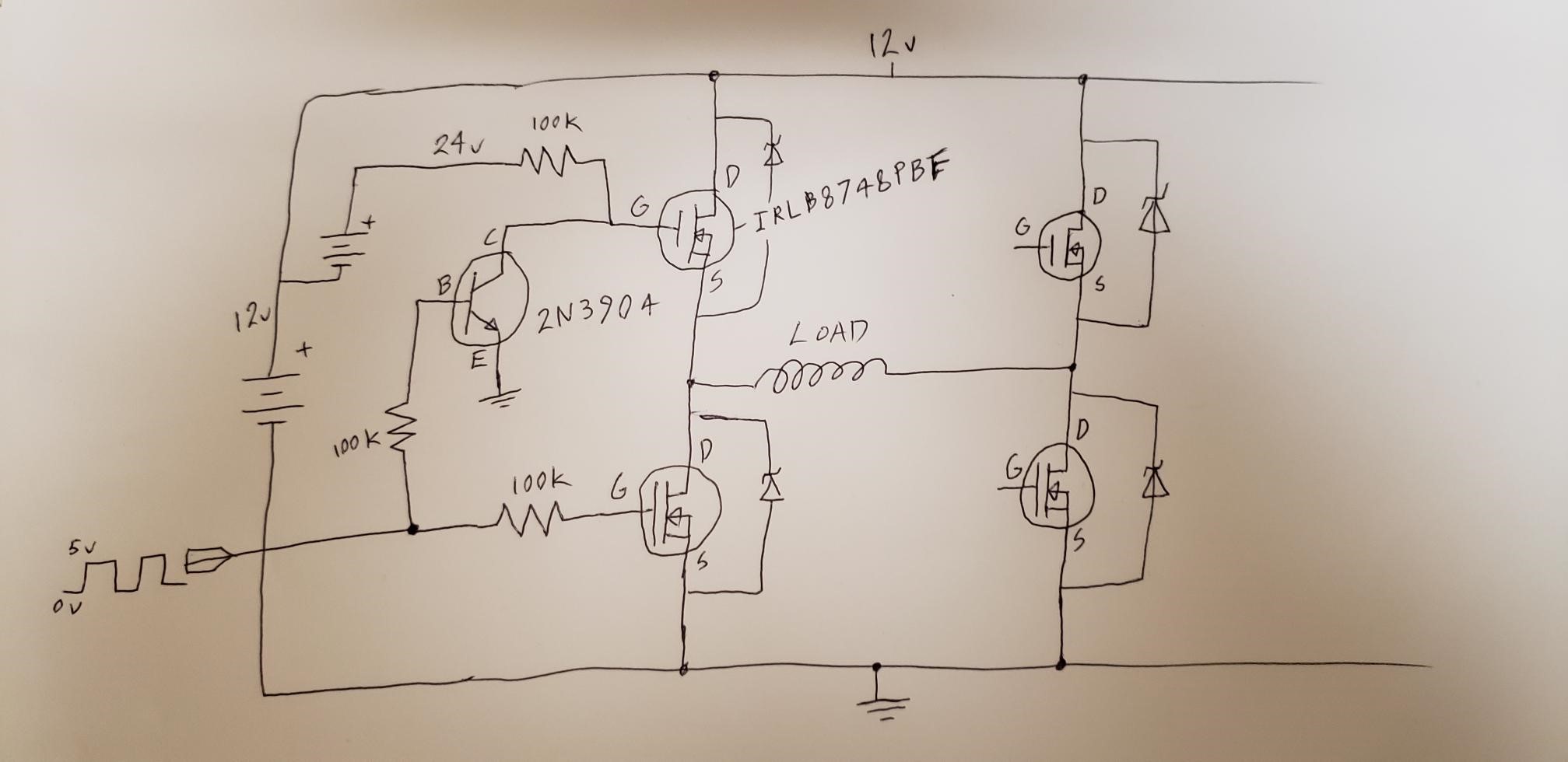
I tested one half of the H-bridge with LEDs as my load. It worked except there was a mysterious clicking noise every time the MOSFETs switch. The right side of the drawing is incomplete. The extra battery is to raise the voltage for the high-side MOSFET gates. Is there anything critically wrong with this design? I may be very confused. Datasheets: https://www.mouser.com/datasheet/2/196/irlb8748pbf-1227971.pdf https://www.mouser.com/datasheet/2/308/2N3904-1118515.pdf

\$\endgroup\$
1
  • \$\begingroup\$ BTW the FETs have internal 'body' diodes, so you don't need external diodes between Source and Drain. \$\endgroup\$ Commented Jan 13, 2019 at 7:46

3 Answers 3

3
\$\begingroup\$

While conceptually your schema would work to turn on a high side FET there are several major issues with it:

  1. You need to ensure that the FET device you use can withstand the +/- voltage across the GS. In your case with the IRLB8748 it can tolerate +/-20V. Other devices might not be able to tolerate this high a drive voltage.

  2. The very high value pullup (turn on) resistor will result in very slow turn on times. In your case the FET has quite high gate capacitance and you have to charge this from 0 to about 16V to turn om the high side FET switch.

  3. The very high base value resistor on the 2N3904 will result in long turn off times for the high side switch. With only uA of base current your transistor will act as a constant current discharge, and with high gate capacitance this takes a long time to turn off the device and could result in significant shoot through current.

Most bootstrap high side drivers can deliver several amps of charge and discharge capability for the FET gate. There is a reason this is done ….it's predictable and fast, and your schema is far from predictable or fast.

I Would strongly recommend you do not use your schema as is without significant changes. Read up on High side drivers as a starting point. Perhaps start here, before deciding how to proceed.

\$\endgroup\$
1
  • \$\begingroup\$ Thank you. I knew something was causing one gate to switch faster than the other which causes this "shoot through" current. That must have been the clicking sound and weird current draws I was seeing. Your explanation is very helpful. \$\endgroup\$ Commented Jan 13, 2019 at 13:57
1
\$\begingroup\$

In addition to Jack's answer, which offers up several valid concerns, clicking in a circuit like this is oftentimes caused by very large currents flowing from V+ (12V in your case) to ground. This generates large magnetic fields which can make things move (generating acoustic noise) and also causes whatever ceramic capacitors are between V+ and ground to emit noises (most ceramic caps are piezoelectric, meaning they can both vibrate in response to voltage and generate voltage in response to vibrations). This often happens when both MOSFETS are briefly "ON" during the switching transition. This can damage MOSFETS either through overcurrent or by generating voltage spikes across the inductance that is an inherent part of the power supply wiring.

\$\endgroup\$
0
\$\begingroup\$

yes that would work. but it may not be very convenient, often some sort of charge pump is used instead of a battery.

\$\endgroup\$
2
  • \$\begingroup\$ Thanks! In my case, the battery may be more convenient because my machine already includes the extra battery. Is the clicking sound probably unrelated to the battery/charge pump issue? \$\endgroup\$ Commented Jan 12, 2019 at 22:50
  • 1
    \$\begingroup\$ The clicking sound could be coming from your load as a result of the current going through it, in which case it may be OK. If it's coming from your board, then Bad Things are probably happening. \$\endgroup\$
    – TimWescott
    Commented Jan 12, 2019 at 23:34

Your Answer

By clicking “Post Your Answer”, you agree to our terms of service and acknowledge you have read our privacy policy.

Not the answer you're looking for? Browse other questions tagged or ask your own question.