2
\$\begingroup\$

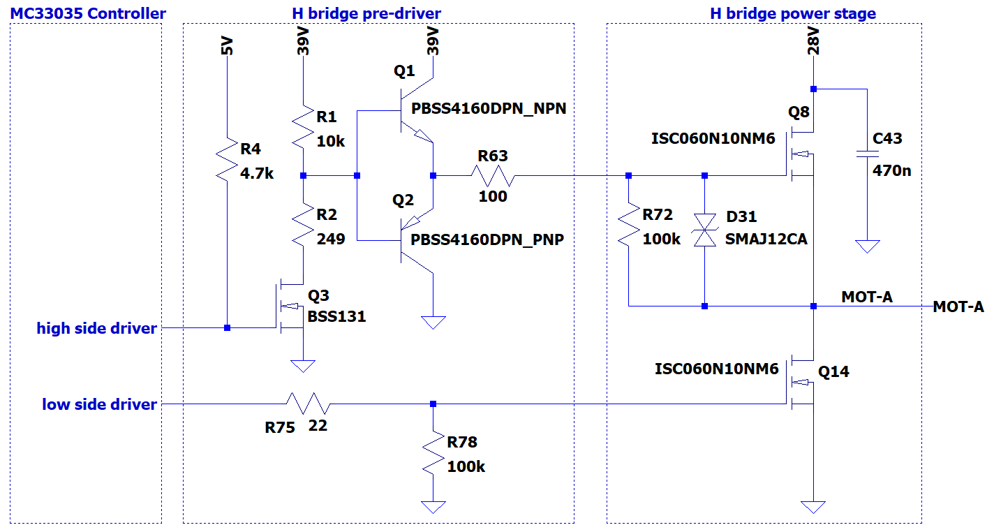
schematic

This H bridge (one leg shown only) drives a three phase brushless motor (each winding is 80mOhm and 38mH). Supply is 16V and total average current consuption 1.3A. The motor is spinning fine. Controller is MC33035.

All the three high side mosfets are overheating, while lower side mosfets are perfectly cold (as expected from a 6mOhm Rdson mosfet). I made some measurements:

  1. high side mosfets Vgs reaches 10V, so they're fully turned on.
  2. high side mosfets Vgs rise and fall time is about 300ns, fast enough.
  3. Vgs measured at high side mosfets gates shows no ringings or oscillations.
  4. there's no cross conduction, otherwise low side mosfets would overheat, too.

What could I investigate to understand why high side mosfets overheat?

EDIT: hereafter the suggested measurements after removing D28, D43 and C46, with a two channel scope.

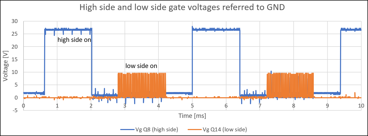
Measurement one: High side and low side gate voltages

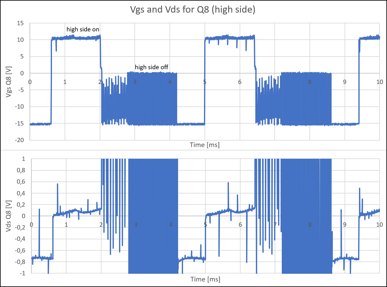
Measurement two: Vgs and Vds for Q8

Measurement three: Current through MOT-A and Vds for Q8

\$\endgroup\$
4
  • 1
    \$\begingroup\$ Please post Vgs and Vds oscillogram of your top MOSFET Q8. \$\endgroup\$
    – winny
    Commented Jul 30 at 23:12
  • \$\begingroup\$ My wild guess would be that your top FETs are turning on too slowly due to the 10 k pull-up and node capacitance at the bases of the BJTs. \$\endgroup\$
    – John D
    Commented Jul 31 at 2:43
  • 1
    \$\begingroup\$ Wouldn't hurt to show low side Vgs as well (shown alongside high side Vgs) to confirm the cross-conduction claim. Similarly, what are the controller signals? Might the controller datasheet be relevant? (A link would be convenient for readers.) \$\endgroup\$ Commented Jul 31 at 4:21
  • 2
    \$\begingroup\$ there's no cross conduction this needs to be verified with not only Vgs, but also with Vds oscillograms of both MOSFETs. And could you please post relevant oscillograms. With fast enough Vgs, if the Vds change is slow somehow (e.g. because of the C46) then you'll have increased losses. \$\endgroup\$ Commented Jul 31 at 6:20

1 Answer 1

0
\$\begingroup\$

"Measurement three" shows that when the high side Q8 was off (check the text on the image) a current was flowing through the mosfet body diode. Indeed current (orange) was negative and voltage (blue) was about -0.7V. This happened because the three motor phases were connected in the wrong order to the board. Surprisingly, I discovered that there are a few phases combinations which can spin a brushless motor, even if, of course, only one is correct.

Connecting the brushless motor phases in the right order solved the overheating problem and reduced current consumption.

\$\endgroup\$

Your Answer

By clicking “Post Your Answer”, you agree to our terms of service and acknowledge you have read our privacy policy.

Not the answer you're looking for? Browse other questions tagged or ask your own question.