2
\$\begingroup\$

I have 900 W (150 W x 6 panels) of solar panels and a 12 V inverter (1000 VA) which has a built-in PWM solar charge controller. The distance between the panels and inverter is >10m and the wires are 6 mm2 only.

At this distance the inverter shows up to 40 A max current from the solar panels and the wire gets quite hot and wastes a lot of power (around 150 W I assume). The panel's voltage is ~18 V, and the voltage at the input to the inverter is ~13-14 V depending on usage.

I tried to reduce the distance to around 4-5 m and the built-in charge controller burned twice (not surprising since the built-in controller has to dissipate more power in this case). Luckily warranty covered me.

So the built-in charge controller is very inefficient; I am getting only max 450-500 W and 350-400 W if average usable power.

I want to design a buck-boost converter for the solar panels so that I can connect panels in series and step down the voltage (15 V or so) at the inverter's input. (Please don't tell me that the built-in controller might burn once again, in the future I will upgrade to a 24 V system and maybe design my own charge controller for lead-acid batteries, so I definitely need a buck-boost converter.)

Now you might ask why buck-boost and why not just a buck converter. I will happily make a buck converter if you give me a design that uses N-channel MOSFETs for low-side switching.

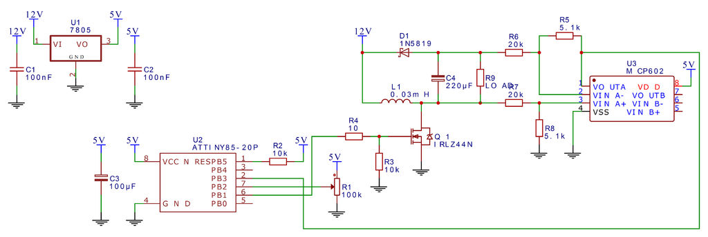
I tried to design one with the schematic from GreatScott and burned my Arduino Nano accidentally as I didn't have a gate driver and applied 12 V to pin D6 of the Arduino accidentally.

Schematic: BuckBoost Schematic Arduino

I didn't use feedback as I was just testing. The circuit worked well in buck mode for a while without heating up too much. I burned my Arduino because I didn't have a gate driver.

So the question is:
Should I use an Arduino Nano (max frequency 63 kHz) or an STM32 microcontroller (>63kHz possible, cheaper) to generate the PWM signal? I will be using IRFZ44N or IRF3205 MOSFETs (the latter one is good).

Please suggest a PWM frequency for keeping switch losses low so that I can get away with using less MOSFETs in parallel; if 63 kHz is enough with reasonable inductor cost, I will go for the Nano blindly.

Please also suggest an inductor value and its current capability. Is 6 μH correct at 63 kHz?

\$\endgroup\$
0

3 Answers 3

1
\$\begingroup\$

I know I am bit late on this, but I think my answer may help.somebody.

Why not give the task of smps to the chip which is designed for it?

Use SG3525 in push pull configuration. Short it's pins 1 and 9. Then supply voltage from 0 to approx 3.6 to its pin 2 to control the duty. You can use the PWM output of uC and have low pass filter ahead to convert the PWM to fixed voltage. Then apply this voltage to pin 2 of SG3525 to control duty cycle. This control voltage can be varied by changing the duty cycle of the uC's pwm.

You can use any uC for this and because the task of smps and drive is offloaded, the uC can focus on other things.

\$\endgroup\$
0
\$\begingroup\$

For your buck converter, how much load regulation and line regulation do you want?

For example, for 12 V output, if you take 1% regulation then you are allowing your output voltage to vary 1% from 12 V during no load to full load.

Speaking about PWM frequency, usually, a buck Cmconverter will range from 100 kHz to even 4 MHz.

However, using digital control it is not possible to go above 63 kHz or 100 kHz without high-resolution PWM. Hence, you should consider STM32F334R8, otherwise you may face stability issues in the closed-loop control.

Your switching loss definitely depends upon the switching frequency but not only on the switching frequency: MOSFET parasitics also play an important role. Based upon your MOSFET you should choose 100 kHz to avoid high switching losses.

For the calculation of the inductance, you can use the Power Stage Designer from Texas Instruments.

\$\endgroup\$
0
\$\begingroup\$

I've done this project a couple year ago using arduino nano. just because at that time I don't familiar with STM. If I be able to do both I would say it doesn't matter, you can choose whatever your want as long as you come up with proper FET, gate driver and filter. What matter is proper gate driver and type of DC-DC convertor. also the component selection.

If we are not talking about the MPPT, the best case scenario are.

  1. The maximum power voltage is around battery voltage.
  2. The allowed battery charging current is greater than PV cells max current.
  3. The invertor can be directly connect with the battery. so there is no need for extra convert.
  4. The charging current of PV controller must greater than load current.
  5. The battery current rate must higher than load current

So, here my question, why PWM charger burnt?

This because your load current is greater than allowed charging current. Maybe it not designed to supply a power during charging as the bottle neck is the charger it self.

As the PWM charger ack more like a switch at bulk charging state. Maybe it doesn't know that it going to over current. It your current draw is temporary peak. Then it a good idea to add OCP as safety feature. Generally, I would suggest that you focussing on upgrade charging current capability with proper cooling. It more straight forward for the problem rather than designing DC to DC convertor.

\$\endgroup\$

Your Answer

By clicking “Post Your Answer”, you agree to our terms of service and acknowledge you have read our privacy policy.

Not the answer you're looking for? Browse other questions tagged or ask your own question.