0
\$\begingroup\$

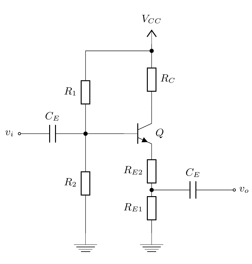
I need to find the output impedance of the BJT amplifier as shown below:

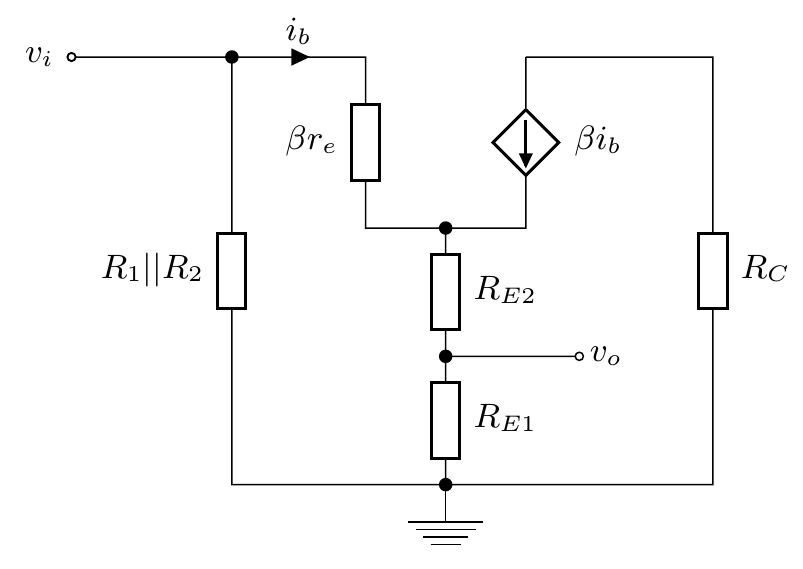
The equivalent small-signal circuit looks like the following:

I know that the output impedance is $$Z_o=R_{E1}\ ||\ (R_{E2}+r_e)\ = \frac{R_{E1}(R_{E2}+r_e)}{R_{E1}+R_{E2}+r_e}$$ but I do not know how to show that. I am fairly new to amplifier circuit analysis. Any help is appreciated.

\$\endgroup\$
3
  • 1
    \$\begingroup\$ Looks homework-ish. What have you learned so far (what's in your "toolkit"), and what's the wording of the homework problem? How do you know what the output impedance is? \$\endgroup\$
    – TimWescott
    Commented Feb 13, 2019 at 0:12
  • 1
    \$\begingroup\$ @TimWescott I study electronics (second year) and this is a problem that was part of an exam from last year. I have the formula for \$Z_o\$ and I know pretty much everything except for how to find the output impedance. The professor's lectures are a mess and he just showed us complete formulas for some specific cases of circuits, with no derivation. The formula for the output impedance is part of the professor's solution, which doesn't contain a derivation either. \$\endgroup\$ Commented Feb 13, 2019 at 0:21
  • \$\begingroup\$ Try to analysis this example electronics.stackexchange.com/questions/295771/… \$\endgroup\$
    – G36
    Commented Feb 16, 2019 at 14:00

2 Answers 2

2
\$\begingroup\$

Just to provide another simple approach:

Looking inward from the output towards the \$R_{\text{E}_1}\$ and \$R_{\text{E}_2}\$ node, you can easily see that it appears that \$R_{\text{E}_1}\$ is tied to a voltage source (ground) and also that \$R_{\text{E}_2}\$ is tied almost to a voltage source, the tip of the emitter (which for all intents and purposes is pretty close to a voltage source that follows the base voltage.) The only difference with \$R_{\text{E}_2}\$ is that the Shockley equation provides that, at AC anyway, there is also an effective AC resistance that is determined by the collector current. (See short analysis here.)

So you have to add \$r_e\$ to \$R_{\text{E}_2}\$ before you get to the effective emitter tip voltage source, at AC. But after adding that in, you then just have \$R_{\text{E}_1}\$ in parallel with \$R_{\text{E}_2}+r_e\$ as the apparent impedance looking inward from that side.

[There are other impedances (as well as capacitances, which are frequency dependent.) One is the source impedance, which will include whatever \$C_\text{E}\$ represents plus the source impedance. But they aren't not mentioned in your schematic. So you get to ignore them. (Had they been mentioned, you could work out a new Thevenin source voltage as well as a slightly different source impedance that includes the source impedance, \$C_\text{E}\$, and \$R_1\:\mid\mid\:R_2\$. And this would add a nuance, after dividing all that by \$\beta+1\$.) But for now, you are allowed to discount it.]

[Keep in mind that in this case \$v_i\$ is considered to be a voltage source (since no additional source impedance is mentioned) and that the current source \$\beta\:i_b\$ has infinite impedance (because you are discounting the Early Effect.) So \$R_\text{C}\$ doesn't matter to these calcs.]
\$\endgroup\$
2
\$\begingroup\$

It is a common assumption in hand analysis to assume the resistance looking into the emitter terminal is \$1/g_m\$ or in your notation \$r_e\$. If you follow this assumption, you will arrive very quickly at the same formula for \$Z_o\$.

A more complete model includes the effect of having finite source resistance. When looking into the emitter terminal, the source resistance appears to be reduced by a factor of \$\beta\$.

In your small-signal schematic you may note that regardless of whether \$R_C\$ is 0 \$\Omega\$ or 1 \$\text{k}\Omega\$ the current is dictated exclusively by the dependent current source.

\$\endgroup\$

Your Answer

By clicking “Post Your Answer”, you agree to our terms of service and acknowledge you have read our privacy policy.

Not the answer you're looking for? Browse other questions tagged or ask your own question.