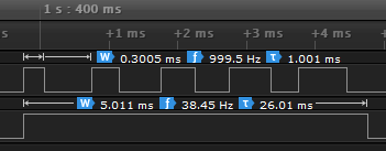
I use the Blue pill STM32F103C8T6 to generate variable duty cycle PWM with DMA and using HAL library. And stuck with undesired results. First, I generated code with STM32CubeMX v5.0.1, HAL v1.7.0, with TIM1 configured to generate PWM on channel 1 with DMA (internal clock, prescaler 71, period 999), and with LED at pin C13 for debugging. The board runs at 72MHz.
Timer initialization:
static void MX_TIM1_Init(void)
{
  TIM_ClockConfigTypeDef sClockSourceConfig = {0};
  TIM_MasterConfigTypeDef sMasterConfig = {0};
  TIM_OC_InitTypeDef sConfigOC = {0};
  TIM_BreakDeadTimeConfigTypeDef sBreakDeadTimeConfig = {0};

  htim1.Instance = TIM1;
  htim1.Init.Prescaler = 71;
  htim1.Init.CounterMode = TIM_COUNTERMODE_UP;
  htim1.Init.Period = 999;
  htim1.Init.ClockDivision = TIM_CLOCKDIVISION_DIV1;
  htim1.Init.RepetitionCounter = 1;
  htim1.Init.AutoReloadPreload = TIM_AUTORELOAD_PRELOAD_DISABLE;
  if (HAL_TIM_Base_Init(&htim1) != HAL_OK)
  {
    Error_Handler();
  }
  sClockSourceConfig.ClockSource = TIM_CLOCKSOURCE_INTERNAL;
  if (HAL_TIM_ConfigClockSource(&htim1, &sClockSourceConfig) != HAL_OK)
  {
    Error_Handler();
  }
  if (HAL_TIM_PWM_Init(&htim1) != HAL_OK)
  {
    Error_Handler();
  }
  sMasterConfig.MasterOutputTrigger = TIM_TRGO_RESET;
  sMasterConfig.MasterSlaveMode = TIM_MASTERSLAVEMODE_DISABLE;
  if (HAL_TIMEx_MasterConfigSynchronization(&htim1, &sMasterConfig) != HAL_OK)
  {
    Error_Handler();
  }
  sConfigOC.OCMode = TIM_OCMODE_PWM1;
  sConfigOC.Pulse = 0;
  sConfigOC.OCPolarity = TIM_OCPOLARITY_HIGH;
  sConfigOC.OCNPolarity = TIM_OCNPOLARITY_HIGH;
  sConfigOC.OCFastMode = TIM_OCFAST_DISABLE;
  sConfigOC.OCIdleState = TIM_OCIDLESTATE_RESET;
  sConfigOC.OCNIdleState = TIM_OCNIDLESTATE_RESET;
  if (HAL_TIM_PWM_ConfigChannel(&htim1, &sConfigOC, TIM_CHANNEL_1) != HAL_OK)
  {
    Error_Handler();
  }
  sBreakDeadTimeConfig.OffStateRunMode = TIM_OSSR_DISABLE;
  sBreakDeadTimeConfig.OffStateIDLEMode = TIM_OSSI_DISABLE;
  sBreakDeadTimeConfig.LockLevel = TIM_LOCKLEVEL_OFF;
  sBreakDeadTimeConfig.DeadTime = 0;
  sBreakDeadTimeConfig.BreakState = TIM_BREAK_DISABLE;
  sBreakDeadTimeConfig.BreakPolarity = TIM_BREAKPOLARITY_HIGH;
  sBreakDeadTimeConfig.AutomaticOutput = TIM_AUTOMATICOUTPUT_DISABLE;
  if (HAL_TIMEx_ConfigBreakDeadTime(&htim1, &sBreakDeadTimeConfig) != HAL_OK)
  {
    Error_Handler();
  }
  HAL_TIM_MspPostInit(&htim1);
}
DMA initialization:
static void MX_DMA_Init(void)
{
  __HAL_RCC_DMA1_CLK_ENABLE();

  HAL_NVIC_SetPriority(DMA1_Channel2_IRQn, 0, 0);
  HAL_NVIC_EnableIRQ(DMA1_Channel2_IRQn);
}
DMA interrupt:
void DMA1_Channel2_IRQHandler(void)
{
  HAL_TIM_PWM_Stop_DMA(&htim1, TIM_CHANNEL_1);
  HAL_GPIO_WritePin(GPIOC, GPIO_PIN_13, GPIO_PIN_RESET);
  HAL_DMA_IRQHandler(&hdma_tim1_ch1);
}
main():
int main(void)
{
  HAL_Init();
  SystemClock_Config();
  MX_DMA_Init();
  MX_TIM1_Init();
  MX_GPIO_Init();

  uint32_t pData[] = {300, 400, 500, 600, 700};

  HAL_GPIO_WritePin(GPIOC, GPIO_PIN_13, GPIO_PIN_SET);
  HAL_TIM_PWM_Start_DMA(&htim1,TIM_CHANNEL_1, pData, 5);

  while (1)
  {
    if (HAL_TIM_PWM_GetState(&htim1) == HAL_TIM_STATE_BUSY) {
          continue;
    }
    HAL_Delay(20);
    HAL_GPIO_WritePin(GPIOC, GPIO_PIN_13, GPIO_PIN_SET);
    HAL_TIM_PWM_Start_DMA(&htim1,TIM_CHANNEL_1, pData, 5);
  }
}
Duty + Idle cycle takes 1ms. Transfer of 5 values lasts for 5 ms. Expecting to have 5 full cycles (duty/idle): 300/700, 400/600, 500/500, 600/400, 700/300. I repeat transfers with pause of ~20ms. Before each transfer C13 is changed to high and after transfer is complete to low (the second channel on analyzer).
There are several problems and possible workarounds (or my mistakes):
First transfer is delayed by one empty cycle in the beginning and the last cycle 700/300 is missing.
WORKAROUND: fill CCR1 (or Pulse value during init) register with pData[0] (partly described in HAL examples), pass &pData[1] to HAL_TIM_PWM_Start_DMA (not stated in HAL examples) and keep length at 5.
The last idle cycle is cut in first transfer and occurred in the beginning of the subsequent transfer. The second transfer starts from idle cycle, left after duty cycle of previous transfer.
WORKAROUND: add extra value (pData[5] = 0) and pass 6 as length to HAL_TIM_PWM_Start_DMA. Then reset CR1 and set EGR registers before each call to HAL_TIM_PWM_Start_DMA.
Eventually I got this:
Is it possible to achieve desired results with HAL without my workarounds and how?


