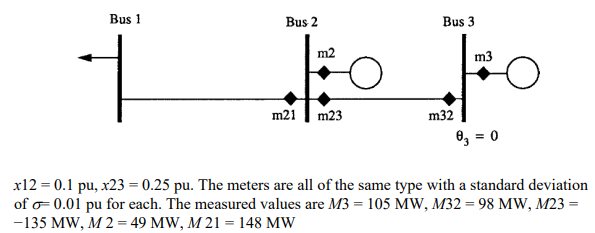
Let the (directed) active power flow at a line connecting buses \$k\$ and \$m\$ be:
$$ p_{km}=\frac{\theta_k-\theta_m}{x_{km}}$$
and denote the power injection at bus \$k\$ by \$p_k\$.
So:
$$
\begin{align}
m_{21} \approx&
\frac{\theta_2-\theta_1}{x_{12}} =&
\frac{-1}{x_{12}}\theta_1 +
\frac{1}{x_{12}}\theta_2 +
0 \theta_3\\
m_{23} \approx&
\frac{\theta_2-\theta_3}{x_{23}} =&
0\theta_1 +
\frac{1}{x_{23}}\theta_2 +
\frac{1}{x_{23}}\theta_3\\
m_{32} \approx&
\frac{\theta_2-\theta_3}{x_{23}} =&
0\theta_1 +
\frac{-1}{x_{23}}\theta_2 +
\frac{1}{x_{23}}\theta_3
\end{align}$$
$$\begin{align}
m_2 \approx& p_2 =&
\frac{\theta_2-\theta_1}{x_{12}}+\frac{\theta_2-\theta_3}{x_{23}} =&
\frac{-1}{x_{12}}\theta_1
+\left(\frac{1}{x_{12}}+\frac{1}{x_{23}}\right)\theta_2 + \frac{-1}{x_{23}}\theta_3\\
m_3 \approx& p_3 =&
\frac{\theta_3-\theta_2}{x_{23}} =&
0\theta_1
+\frac{-1}{x_{23}}\theta_2 + \frac{1}{x_{23}}\theta_3
\end{align}$$
Then the numbers multiplying the voltage angles are the elements of your matrix so that
$$\begin{bmatrix}
m_{21}\\m_{23}\\m_{32}\\m_2\\m_3
\end{bmatrix}
\approx B
\begin{bmatrix}
\theta_1\\\theta_2\\\theta_3
\end{bmatrix}
$$
You should also specify a reference bus \$s\$ to have \$\theta_s=0\$, then you can remove the corresponding column of \$B\$.
I'm thinking: M2 = M12 + M23 (should one be negative even though both are flowing out of bus 2?)
I think you are making a mistake by thinking this in terms of measurements. The external injection into bus 2 (which should match the measurement M2) equals the network flows out of bus 2. So it would be better to write \$p_2=p_{21}+p_{23}\$.
Note that I wrote \$p_{21}\$, not \$p_{12}\$, so net power into (or out of) the bus is zero.
M3 = M32 (do we consider M23 here at all?)
\$p_3\$ does equal \$p_{32}\$ from nodal power balance. I'm not sure what you mean by "do we consider M23 here at all?", as this is a lossless model where the flow \$p_{km}=-p_{mk}\$. You are probably asking this because you are not making a proper distinction of measurements and actual flows due to voltage angles.

