1
\$\begingroup\$

I'm trying to convert a voltage that is between -5V and +5V to the range of 0...5V. These voltages can be found in "euroracks"/"doepfer a100"-systems which are modular synthesizers for music.

This conversion is possible with the schematics found at https://masteringelectronicsdesign.com/design-a-bipolar-to-unipolar-converter/

With a TL074 opamp this works fine on my breadboard.

Now there is a problem with that: the input-voltage for my use-case (eurorack/a100 modules) can be -12...12V in some cases. In that case (e.g. anything that is outside -5...5V) I would like to clamp it to -5...5V. Limitting to +5 I can do with a LM336Z-5.0 I think but how can I protect against voltages lower than -5V? (or less than 0V after conversion)

The signal I'm converting is a voltage that represents a frequency. E.g. 3.250V is note C4 see wikipedia

The output will be send to an arduino adc pin.

\$\endgroup\$
14
  • 1
    \$\begingroup\$ @SunnyskyguyEE75 it is for audio so millivolts I think. i'll add that tot the question itself, i get the feeling that that may be important \$\endgroup\$ Commented Feb 26, 2019 at 19:36
  • 1
    \$\begingroup\$ TL 074 = Supply voltage –0.3 to 36 so no problem with using Schottky diodes to both rails +5V and 0V then inject 5V offset and gain =1/2 \$\endgroup\$
    – D.A.S.
    Commented Feb 26, 2019 at 19:39
  • 2
    \$\begingroup\$ ah, so it's not audio then? \$\endgroup\$ Commented Feb 26, 2019 at 19:44
  • 2
    \$\begingroup\$ @FolkertvanHeusden the diode isn't in series with the signal: It's just one each in "normally blocking" direction to ground and to supply voltage: in case of overvoltage, that diode would conduct. \$\endgroup\$ Commented Feb 26, 2019 at 19:46
  • 2
    \$\begingroup\$ @FolkertvanHeusden so, audio signals are signals in the audible range of frequencies, your's is not :) \$\endgroup\$ Commented Feb 26, 2019 at 19:46

4 Answers 4

3
\$\begingroup\$

schematic

simulate this circuit – Schematic created using CircuitLab

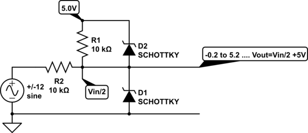
No Amp required. This attenuates to Vin/2 with a 5.0V offset to centre the output to V+/2

Anything |Vin| >5.2V clips with low current from 10k//10k effective series resistance.

Otherwise if |Vin| < 5V diode is high impedance (off).

If input impedance is 1M then the actual signal is attenuated 5k/1M*100%=0.5% which is less than 1% tolerance of R1,R2

\$\endgroup\$
4
  • \$\begingroup\$ The point where the box is with '5.0V' means that I have to insert 5V at that point? Same question for the Vin/2-box. \$\endgroup\$ Commented Feb 26, 2019 at 20:13
  • 1
    \$\begingroup\$ If your inputs only accept 0 to 5V input then you need a 5V reference or supply . Vin/2 is just a test point where you see Vin= +/-5 reduced to 2.5 +/-2.5V and anything larger is clipped. Is that what you need? \$\endgroup\$
    – D.A.S.
    Commented Feb 26, 2019 at 21:00
  • \$\begingroup\$ Hi, I've simulated it in circuitjs (tinyurl.com/y4woc4en ) and it looks like its output ranges from -0.4 to +5.4. I don't think the arduino adc will like that :-) Is it possible to adjust the minium and maximum voltages? \$\endgroup\$ Commented Mar 20, 2019 at 15:49
  • 1
    \$\begingroup\$ @FolkertvanHeusden That's why CMOS uses special Schottky diode pairs to each rail with 10K in between on inputs. Their low current rating of 5mA makes them small and faster than the CMOS and fast enough for ESD. You only have 2 Schottky builtin options in that simulator \$\endgroup\$
    – D.A.S.
    Commented Mar 20, 2019 at 16:36
1
\$\begingroup\$

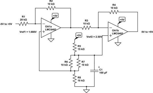
A low output impedence version...

schematic

simulate this circuit – Schematic created using CircuitLab

The LMC6482AIN is a dual rail to rail input and output op amp.

\$\endgroup\$
1
  • \$\begingroup\$ Hi James. Am I right that without the buffering the schematic is tinyurl.com/y6bpkryn ? In that case: it is clipping the voltage, not shifting and reducing. \$\endgroup\$ Commented Mar 20, 2019 at 16:22
0
\$\begingroup\$

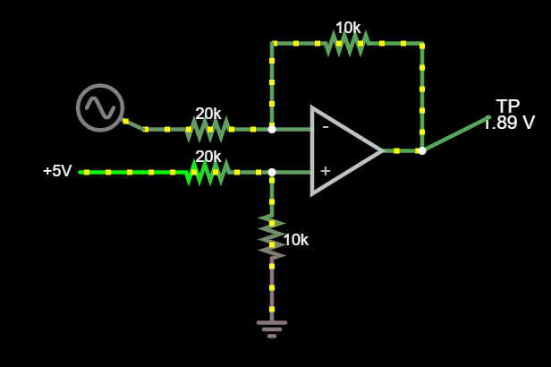
I've been spending some time with circuitjs and I think this is what I want:

schematic in circuitjs

schematic picture

Any voltage between -5V and +5V is scaled and shifted to 0...5V. Furthermore anything outside that range is clipped.

\$\endgroup\$
0
\$\begingroup\$

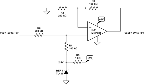
This is a good solution but I have to give most of the credit to Spehro Pefhany who posted a similar circuit on a different thread.

schematic

simulate this circuit – Schematic created using CircuitLab

The TL431 is configured to give a 2.5V reference by tying its REF pinto its Cathode pin.

\$\endgroup\$

Your Answer

By clicking “Post Your Answer”, you agree to our terms of service and acknowledge you have read our privacy policy.

Not the answer you're looking for? Browse other questions tagged or ask your own question.