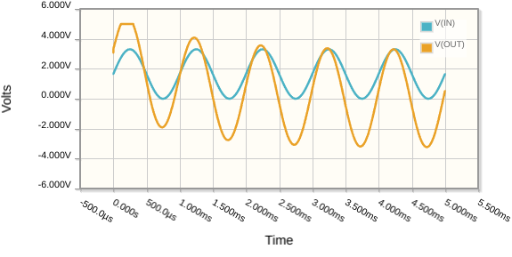
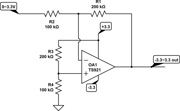
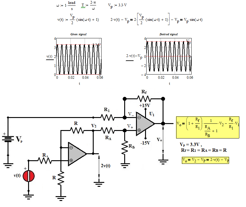
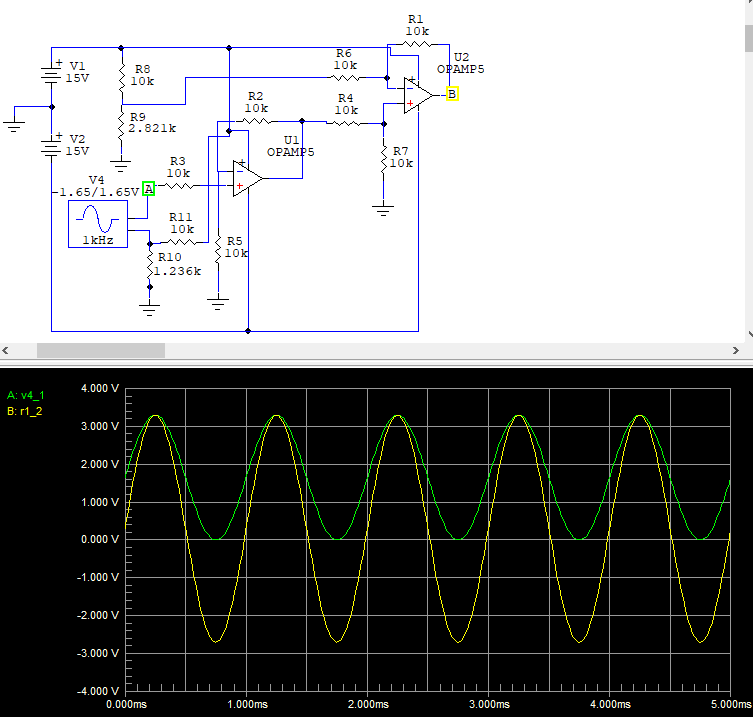
Even a rail-to-rail output op-amp cannot quite get its output all the way to the rails. It will always fall a few millivolts short. Many op-amps can't handle inputs that get too close to their supply rails either. Check your op-amp's datasheet, but to be safe with most op-amps you'll need to supply the op-amp with well beyond ±3.3V.
Assuming you can do that, with say ±5V, then try this:
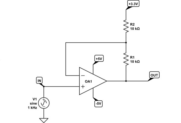
simulate this circuit – Schematic created using CircuitLab
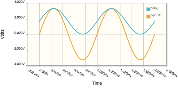
Update: How I derived those values.
There's a relationship between \$V_A\$, \$V_B\$ and \$V_{OUT}\$ for the following generic circuit:

simulate this circuit
The formula is:
$$ V_{OUT} = V_B\left( 1 + \frac{R_2}{R_1} \right) - V_A\frac{R_2}{R_1} $$
Find two conditions that you know to be true:
- \$V_{OUT} = 0V\$ when \$V_B=+1.65V\$
- \$V_{OUT} = +3.3V\$ when \$V_B=+3.3V\$
Plug those values into the formula to obtain two simultaneous equations:
$$ 0 = +1.65\left( 1 + \frac{R_2}{R_1} \right) - V_A\frac{R_2}{R_1} $$
$$ +3.3 = +3.3\left( 1 + \frac{R_2}{R_1} \right) - V_A\frac{R_2}{R_1} $$
Solve them to reveal two quantities, \$V_A\$ and the ratio \$\frac{R_2}{R_1}\$. Choose any two resistances in that ratio within reason. Keep them in the kilohms, for these reasons.
The word "suitable" is subjective. The above design will work fine if you're sure the power supply is stable, exactly +3.3V, and sufficiently free of noise. Any design (like the one above) that uses the power supply as a voltage reference is going to inject any offset or noise present on the supply directly into the signal.
To avoid this you'll need a precision voltage regulator, like the TL431, like this:
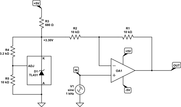
simulate this circuit
If you know the lowest frequency your DAC will ever produce, then you can get the simplicity of my first proposal and the accuracy (zero offset) of my second, using an RC high-pass filter:
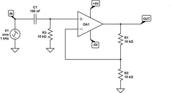
simulate this circuit
Capacitor C1 and resistor R3 are used to "AC couple" the signal. This removes any DC offset, so it becomes centered around zero volts (ground). Then all the amplifier needs to do is multiply by 2.
It has the disadvantage that the signal takes some time, about \$5C_1R_3\$ to settle at its final offset. If the lowest frequency you expect from your DAC is \$f_{MIN}\$, then you should aim for a cut-off frequency of significantly less, say by a factor of 10, \$f_C=\frac{f_{MIN}}{10}\$. Then C1 and R1 will be chosen such that:
$$ C_1R_3 = \frac{1}{2\pi f_C} $$
