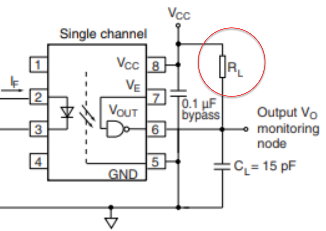
Consider the following reference circuit for a 6N137 optocoupler. My understanding is that this circuit uses a pull-up resistor on the output node so when the optocoupler led is activated, the transistor gate opens and the output is pulled to ground. This seems to be a standard configuration for open-collector or open-drain circuits. What puzzles me is that it seems inefficient. In order to switch the output off, I need to effectively short the circuit in order to pull it to ground. Is my interpretation correct? If not, why not?
3 Answers
You are correct (except that when the LED is activated, the phototransistor gate is injected with current. It's the opposite logic of what you said). It has it's uses though such as flexible output voltages and inherent ORing of signals.
ADDED:
Using a large resistor minimizes current consumption when the output is pulled LO, but also increases the time it takes to charge the parasitic capacitances on the line and and input capacitances so your rise times get slower which might be unacceptable for some applications (the most common one is a serial bus like I2C).
-
\$\begingroup\$ What do you mean by "inherent ORing of signals" ? \$\endgroup\$ Commented Mar 2, 2019 at 21:26
-
1\$\begingroup\$ You can connect multiple open collector outputs to a line with one-pull-up resistor and if any output pulls it low, the entire line goes low without the outputs fighting each other.. Logic OR...technically NOR. \$\endgroup\$– DKNguyenCommented Mar 2, 2019 at 21:31
-
\$\begingroup\$ I'd add that if you use a fairly large resitor, 10k or 100k, the wasted current in the resistor is negligible compared to the energy wasted in the optocoupler LED \$\endgroup\$– TemeVCommented Mar 3, 2019 at 7:45
-
\$\begingroup\$ @TemeV Yes, OTOH, the time to charge the parasitic capacitances of the line and of the input will be increased so you might not reach your rise time requirements. \$\endgroup\$– DKNguyenCommented Mar 3, 2019 at 19:00
-
\$\begingroup\$ @Toor yes that is also true. As always, you have to choose the compoment so that it fits to the requirements. The components are always a trade off of something. In this case flexibility and price has been prioritized over efficiency / switching speed (leaving the efficiency vs. switching speed trade off for the user) \$\endgroup\$– TemeVCommented Mar 4, 2019 at 5:59
What puzzles me is that it seems inefficient. In order to switch the output off, I need to effectively short the circuit in order to pull it to ground. Is my interpretation correct? If not, why not?
Figure 1. The opto-isolator's output is shown with RL, the load.
What you are missing is that RL is the load. When the output is pulled low there is voltage across RL and power is consumed. When the output is high there is no voltage across the load so no power is consumed.
This arrangement works fine for certain designs but, as you suspect, it would waste power if, for example, it was only driving a CMOS input. In that case a push-pull arrangement would be much more efficient.

simulate this circuit – Schematic created using CircuitLab
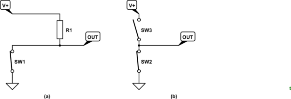
Figure 2. Simplified representation of open-collector/drain output and push-pull outputs.
- Figure 2a has no internal means of pulling the output high so the pull-up resistor, R1 is required. Current draw is determined mostly by the value of R1.
- Figure 2b can pull high or pull low. In the steady state the current draw is determined by the input impedance of the next stage. This is potentially much more efficient.
-
\$\begingroup\$ Ah, interesting. Would a push-pull configuration have comparable switching latency to a canonical open-collector or open-drain circuit? \$\endgroup\$ Commented Mar 2, 2019 at 22:20
-
\$\begingroup\$ I'm the wrong guy to ask. It's never been an issue on the speeds that I work at. I would imagine that for an opto device the latency will be determined much more by the opto part than by the logic part. You might find a push-pull type in the same range and be able to compare specifications. \$\endgroup\$ Commented Mar 2, 2019 at 22:44
What is output efficiency for an open drain or open collector?
Let's look at the output power dissipation.
When the LED input current is ON, it depends on pullup load \$P_R =\dfrac{(Vcc-Vout)^2} {R}\$.
When the LED input current is OFF, there is only 1uA load current MAX and typically less with no other loads.
Pasted from datasheet...
Low level output voltage VE = 2 V, If = 5 mA, IOL (sinking) = 13 mA VOL - 0.2typ 0.6max V
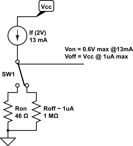
The output transistor has an equivalent resistance when ON
ΔV/ΔI= Vol/If= 0.6maxV/13 ma (sinking) = 46 Ω (max) , 200mV/13mA= 15 Ω (typ)
So have the following equivalent circuit for input If=5mA

simulate this circuit – Schematic created using CircuitLab
Thus the datasheet recommends
RL 330 (min) 4 kΩ (max)
This affects your speed and fanout but power dissipation of my 1st formula applies.
So one might use 3.3V with 330 Ω or 10mA for max speed and 5V with 1kΩ (5mA) for less power or 4kΩ for least power but slowest speed.
-
4\$\begingroup\$ I think maybe because it didn't answer OP's question. He's just asking if pull-up resistors and open-collector outputs consume current when outputting a LO. \$\endgroup\$– DKNguyenCommented Mar 2, 2019 at 21:33
-
\$\begingroup\$ "An emitter follower, for example, will not pull any current to anode LED". What do you mean by that? (For the record, I'm an electronics novice and always appreciate the time people take to provide their insight, even if it isn't always on the mark). \$\endgroup\$ Commented Mar 2, 2019 at 21:36
-
3\$\begingroup\$ It's almost like you're reading a different question. \$\endgroup\$– DKNguyenCommented Mar 2, 2019 at 21:42
-
2\$\begingroup\$ Again, your comments seem completely off-base from what the question is asking. He's asking about the OUTPUT of the optocoupler whereas you're weirdly focused on the LED drive at the input and the photoreceiver. His question is about open-collector outputs in general, not optocouplers. Perhaps you mistook him for wanting to ask about the open emitter or collector drive of the LED (something that is neither shown nor implied in his schematic)? \$\endgroup\$– DKNguyenCommented Mar 2, 2019 at 21:52
-
1


