1
\$\begingroup\$

I'm designing a simple circuit where I intercept and read an open collector pulse signal from an external machine and let it pass through to an optocoupler. In addition to that, I can also output a pulse signal through my MCU. The external machine's optocoupler is set in a normally open configuration. My circuit is as follows.
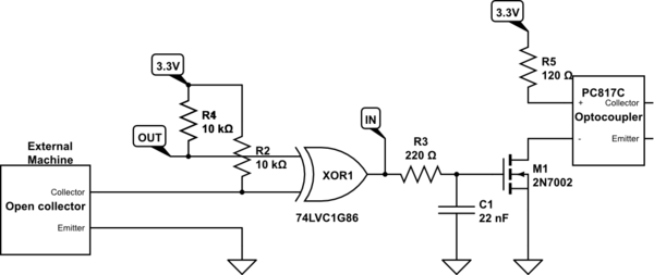
schematic

simulate this circuit – Schematic created using CircuitLab

This circuit works most of the time but currently, I'm facing some instability issues that are inconsistent.

  1. The voltage across the external machine's collector and emitter read 0.6V instead of 3.3V. When a pulse is sent through, the voltage will pulse between 0.6V and 0V which is too low to trigger the XOR gate.
  2. The idle voltage is 3.3V but when a pulse comes through, it drops to zero and slowly rises over a period significantly longer than the pulse. (eg. pulse is 50ms, it drops for 3s)

These issues do not happen consistently but when it does it prevents the input signal from passing through to the output optocoupler. Can anyone help explain what is happening in this situation?

\$\endgroup\$
2
  • 1
    \$\begingroup\$ Sounds like a bad/intermittent/high-resistance connection to the pull-up resistor on the output of the external machine. \$\endgroup\$
    – John D
    Commented Apr 23, 2023 at 19:16
  • \$\begingroup\$ You should check both the external machine and the logic gate for failure. Also, your schematic is a bit unclear, you have marked a logic gate input with OUT. Please include picture(s) of your setup and connections, as well the models of your sensors. \$\endgroup\$ Commented Apr 23, 2023 at 20:57

1 Answer 1

1
\$\begingroup\$

If the following conditions are true:

  1. Your "external machine" truly does have an open-collector output, and that transistor is working normally

  2. The emitter of that same transistor is connected to ground

  3. You have a 10kΩ resistance between collector and +3.3V

  4. The only other thing connected to the collector is a working XOR gate input

then you absolutely should have a collector potential that goes between almost-ground (about 0.1V) and +3.3V.

So if you don't see those two possible conditions, then one of the above things is false.

With the collector potential clamped to a maximum of 0.6V, I suspect input protection diodes of the XOR gate are clamping the signal to ground. That would happen if the power supply (Vdd/Vcc) to the 74'86 IC is 0V, or broken or intermittent. Check that the Vdd/Vcc pin of the XOR IC is at least +3V.

A rise time of 3s is what would happen if R2 were not there. Check that it really is 10kΩ, and that it's properly connected at both ends.

Something that both these symptoms have in common is the +3.3V supply, so that's where I would check first. The slow rise time would suggest that the supply is physically disconnected, not just at 0V.

\$\endgroup\$
2
  • \$\begingroup\$ Based on the datasheet of the external machine, it uses a PC814 optocoupler as the open collector output. The 74'86 IC is supplied with a 3.3V including a decoupling capacitor. The 3.3V supply comes from a TPS54202 buck converter which is powering the rest of the components including the MCU that is not giving any problems. \$\endgroup\$
    – Max
    Commented Apr 24, 2023 at 15:01
  • \$\begingroup\$ @Max sorry to say, I don't see anything wrong with the schematic, barring things you're not showing, so I think this is not a design issue. I'm forced to conclude that the problem is a fault with something here. I hope you pin it down, the little gremlin! \$\endgroup\$ Commented Apr 24, 2023 at 16:09

Your Answer

By clicking “Post Your Answer”, you agree to our terms of service and acknowledge you have read our privacy policy.

Not the answer you're looking for? Browse other questions tagged or ask your own question.