1
\$\begingroup\$

I am having 100% failure rate trying to get this high side driver to operate. The failure happens as soon as the 5v logic signal is turned on. I have had straight shorts from VDD to GND, and I have had burnt smoking chips. I am clearly doing something incorrectly.

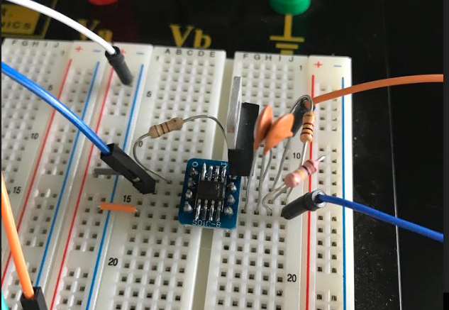
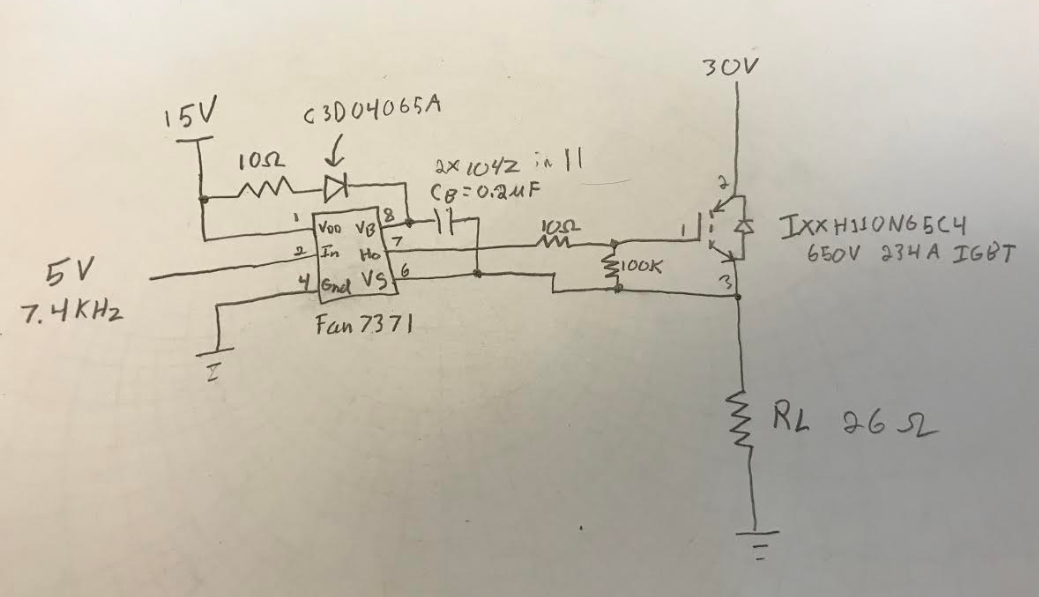
Following the schematic i made:

enter image description here

The driver datasheet is: Fan7371

https://www.onsemi.com/pub/Collateral/FAN73711-D.pdf

Diode data sheet: c3d04065A

https://www.wolfspeed.com/downloads/dl/file/id/841/product/46/c3d04065a.pdf

Power supplies used:

tektronix PWS2323 DC power Supply 0-32V, 3A

IGBT data sheet: IXXH110N65C4

https://www.littelfuse.com/~/media/electronics/datasheets/discrete_igbts/littelfuse_discrete_igbts_xpt_ixxh110n65c4_datasheet.pdf.pdf

last circuit the 10ohm Rboot (replaced with 100 ohm in picture) burnt out and then the driver when I was noticing that the capacitors were discharging when VDD was turned off. Pretty sure this should not happen.

enter image description here

EDIT:

The circuit will eventually be run at much higher voltage which is why the overkill on some of the parts.

The pins are correct on the IGBT. orange wire going to 1 (G) and blue going to 3 (S)

In response to the answer:

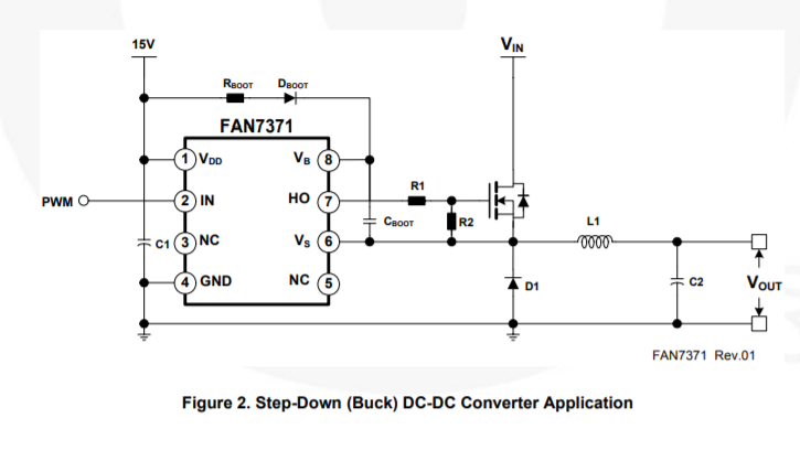
Similar to this typical setup from the data sheet.

typical buck configuration from data sheet

If i add a diode from source to ground would that provide a better result? It was my thinking that CB was able to find the off time charge path through the load ground. when i turn the first supply on it has no trouble charging to 15 volts, but CB does discharge immediately if i turn it off as well.

\$\endgroup\$
4
  • \$\begingroup\$ What does burn in this failure mode which you're having: the IGBT, or the gate driver? \$\endgroup\$ Commented Apr 1, 2019 at 19:11
  • \$\begingroup\$ Can't be sure from the angle of the photo, but it looks like IGBT pins 1&3 are reversed on the breadboard. For example, the caps are connected to IGBT pin G. \$\endgroup\$
    – scorpdaddy
    Commented Apr 1, 2019 at 19:26
  • \$\begingroup\$ Can you take a better photo so we can see where the transistor is connected? \$\endgroup\$
    – HandyHowie
    Commented Apr 1, 2019 at 19:31
  • \$\begingroup\$ You crammed in everything quite close together, it is impossible to see if there are any accidental shorts or if you connected everything correctly. To prevent the "magic smoke" escaping, use a lab supply with current limiting and set the maximum current to 100 mA for example to prevent damage. \$\endgroup\$ Commented Apr 1, 2019 at 19:32

1 Answer 1

1
\$\begingroup\$

(1) Get rid of that 10 ohm resistor in series with the boostrap cap. It's slowing down the refresh of your bootstrap cap.

(2) Add decoupling capacitors between Vdd-GND

(3) Increase the size of your boostrap cap to 1 or 10uF. You may still want to keep a 0.1uF in parallel with that for decoupling.

(4) Your C3D04065A is major overkill. That doesn't ever see more than 15V. You could get away with a 1N4448 here if you wanted to.

(5) This part here is important: Bootstrap capacitor high-side drivers cannot run on 100% duty cycle and require the floating drain terminal to be periodically pulled low to refresh the bootstrap cap. This is usually performed by turning on the low-side transistor in the half-bridge through regular operation...but you don't have that in your circuit, so you have a problem. You need to review what a bootstrap circuit actually does and re-design your circuit accordingly (it would involve too much changes to walk you through it as is without you deciding on the approach you want to take first).

(6) IGBTs also sometimes require application of a slightly negative gate voltage relative to the drain, in order to actively drain the charge, for reliable turn-off (unlike a MOSFET).

\$\endgroup\$
2
  • \$\begingroup\$ Also, IGBTs are appropriate with high currents, or high voltages. This circuit has neither issue, so far as I can tell. Better off with a MOSFET (or BJT) with a far less boutique driver circuit, I suspect. \$\endgroup\$
    – jonk
    Commented Apr 1, 2019 at 20:40
  • \$\begingroup\$ The circuit will eventually be at a much higher voltage. 500V 20 A and set to run continuously via transformer or charge pump on CB to keep it charged. \$\endgroup\$
    – Les
    Commented Apr 1, 2019 at 22:35

Your Answer

By clicking “Post Your Answer”, you agree to our terms of service and acknowledge you have read our privacy policy.

Not the answer you're looking for? Browse other questions tagged or ask your own question.