1
\$\begingroup\$

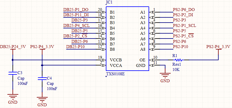
I'm using a TXS0108E to convert from 5V to 3.3V and vice versa. The schematic is below:

enter image description here

In the datasheet, in section 6, I read the following:

Voltage applied to any output in the high-impedance or power-off state, VO:

A port :

     MIN: –0.5V
     MAX: 4.6V 

B port:

     MIN: –0.5V
     MAX: 6.5V

Voltage applied to any output in the high or low state, VO

A port:

    MIN: –0.5 
    MAX: VCCA + 0.5 V

B port:

    MIN: –0.5 
    MAX: VCCB + 0.5 V

Some of pins in B port are energized when the IC is not powered at all. So I was wondering, would this be a problem ? Normally it is a problem to ICs, would this IC be a exception ?

\$\endgroup\$
3
  • 1
    \$\begingroup\$ I suggest that you have a look at this video explaining how an IC can be powered through any of its inputs due to the ESD protection: youtube.com/watch?v=2yFh7Vv0Paw&t=6s that might not directly damage the IC but can lead to unexpected behavior. It is unclear to me if the TXS0108E has similar ESD protection. You can find out by using a multimeter's diode test between VCCB and one of the inputs. \$\endgroup\$ Commented Apr 3, 2019 at 13:45
  • 1
    \$\begingroup\$ The fact that the specification is the same for Hi-Z and power-off is a clue; the H-Z control may act that way in the power down state. \$\endgroup\$ Commented Apr 3, 2019 at 13:51
  • 2
    \$\begingroup\$ Note that this is not an "ordinary" digital IC. Because it's specifically designed as a level converter it is likely that the I/O circuitry is different than what you would normally expect in for example an MCU or a 74-series logic. \$\endgroup\$
    – pipe
    Commented Apr 3, 2019 at 14:05

2 Answers 2

1
\$\begingroup\$

Absolute Maximum Ratings indicate limit that will not cause any damage to the device, but don't mean that it will behave properly at those limits. Most devices have clamp diodes for ESD that can allow a voltage at any pin to unintentionally energize the device. The datasheet says

To ensure the Hi-Z state during power-up or powerdown periods, tie OE to GND through a pull-down resistor. The minimum value of the resistor is determined by the current-sourcing capability of the driver.

so I'd guess that so long as this is observed, the chip should behave as intended, i.e. do nothing with an input while not powered.

You do need to take care that there are no loads on the Vcc lines that can draw current back through the protection diodes.

\$\endgroup\$
1
  • \$\begingroup\$ Yes, I understood. But, in my design I put OE connected to VCC 3.3V through a resistor of 10K. So, maybe is better to connect the OE pin directly to the VCC 3.3V and change the resistor to a pull-down resistor. What do you think ? \$\endgroup\$
    – Daniel
    Commented Apr 3, 2019 at 14:09
1
\$\begingroup\$

The datasheet tells you that you should not have any of the pins on B side high when Vcc B is not present. Vcc A does not matter.

In your situation you should use a different chip or circuit that is guaranteed high-Z with Vcc B not present. Series resistors, sometimes used as a hack, are not compatible with the so-called automatic data direction scheme.

\$\endgroup\$
4
  • \$\begingroup\$ This is a valious information, but, where in datasheet is saying this ? \$\endgroup\$
    – Daniel
    Commented Apr 3, 2019 at 14:12
  • 1
    \$\begingroup\$ Your situation is Vcc B = 0, so pins on that side should be no more than 0.5V. \$\endgroup\$ Commented Apr 3, 2019 at 14:13
  • 1
    \$\begingroup\$ And about the specification : "Voltage applied to any output in the high-impedance or power-off state" of section 6.1 Absolute Maximum Ratings ? \$\endgroup\$
    – Daniel
    Commented Apr 3, 2019 at 14:18
  • 1
    \$\begingroup\$ Somewhat confusing specification, it might be okay but it does not seem clear to me. You might want to consult TI forums and get an official answer before designing a PCB. Personally, I would move on to another part- not a big fan of automatic direction circuits as we've been bitten. \$\endgroup\$ Commented Apr 3, 2019 at 14:27

Your Answer

By clicking “Post Your Answer”, you agree to our terms of service and acknowledge you have read our privacy policy.

Not the answer you're looking for? Browse other questions tagged or ask your own question.