I'm an electronics engineering student and I want to state that this question is not my homework, it is a tiny part of my project (PWM encoder) but I couldn't pass it.
I'm trying to make a "frequency to voltage converter" but 3 days of web search didn't allow me to do that. (Seriously, even in SE there are no clear topics about frequency to voltage converters) I know some ICs can do that but I want to do my project without any IC, using only primitive components so I tried RC low-pass filter as an integrator to make frequency to voltage converter.
The input is a square wave between 10-20kHz
Design objectives are :
The converter should handle frequencies between (all frequencies at that range) 10kHz and 20kHz.
And it should converge under 10 cycles
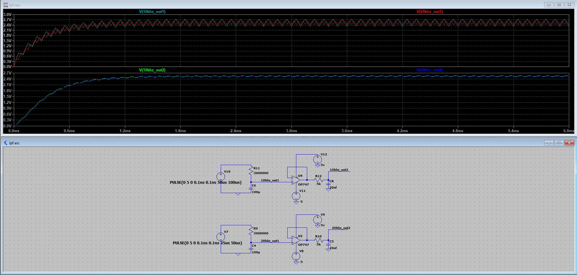
I made 2 different circuits and simulated but in first circuit output voltages are the same and they are not converging fast enough.
Here is the first circuit scheme and simulation results:
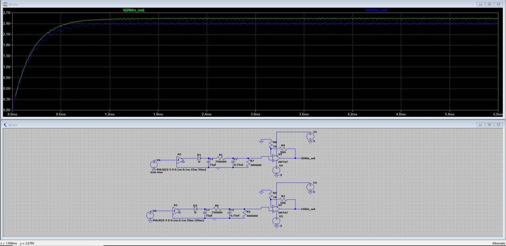
And in second circuit output voltages are different but too close, I need like 4 volts for 20kHz and 2 volts for 10kHz. How can I separate them? And again it is not converging fast enough.
Here is the second circuit:
To be honest, I took the left-hand side circuit from the internet and couldn't understand the principle behind it. The diode was between the schmitt output and ground (parallel to the first capacitor) but since I don't know its purpose, I tried different combinations and decided that this version is better.
In both circuits, the more outputs separate, the more time needing for converge and more ripples occur. Is it always a choice between one or another? Are there some ways to make it better?
I am not wanting full solution or design (if you can provide I'll appreciate), I'm just asking for guidance and tips/tricks.
Edit : Additional Information
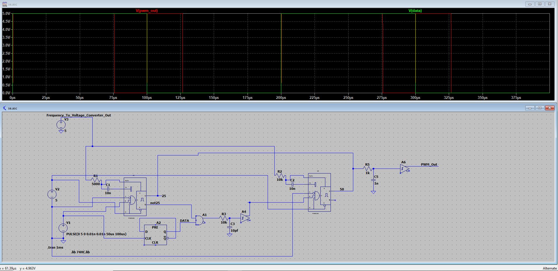
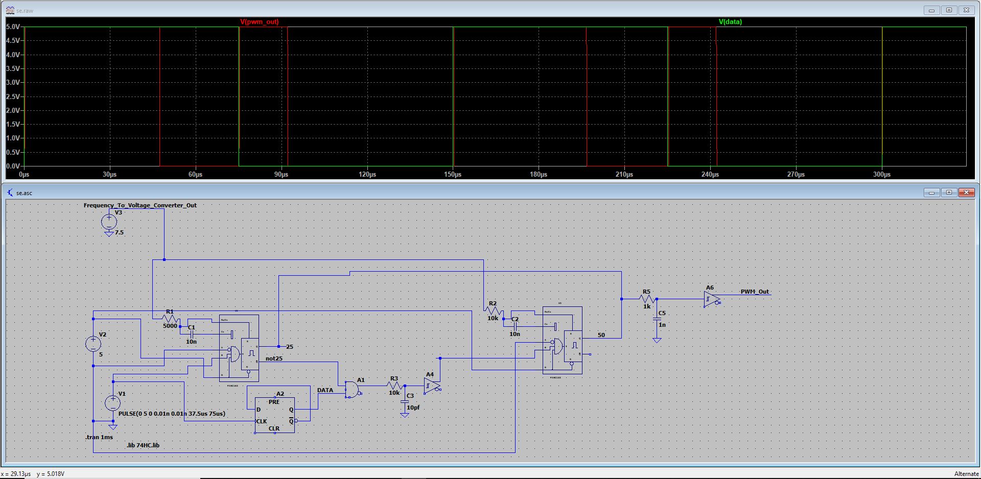
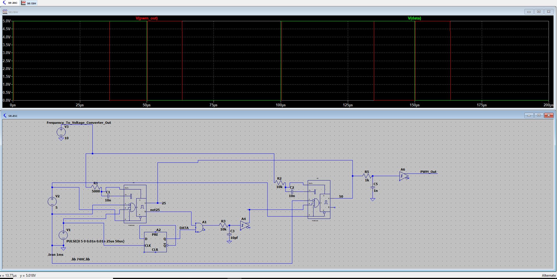
The circuit below is designed for PWM encoder which generates 25% pulse width for data "0" and 75% for data "1" between 10-20kHz. Monostable Multivibrator(MMV) pulse width is depended on RC on its Rx, Rx/Cx pins and the voltage on the RC part. The Difference between the three images below are clock frequency(first is 10kHz second is 15kHz the last one is 20kHz) and the voltage on RC (Top left Voltage source will be replaced by Frequency-To-Voltage Converter) are 5v, 7.5v, and 10v respectively. These three values are for example. I need correct voltage on RC part for every frequency so I need to obtain voltage value from clock signal. The question is about it, how can I obtain voltages between 5-10v as precise as possible by connecting Frequency-to-Voltage converter between MMV's RC part and clock signal.

4 volts for 20kHz and 2 volts for 10kHzto thedesign objectivessection \$\endgroup\$