0
\$\begingroup\$

Say I have a 9V supply, and I want to power an LED that requires 3V and 0.02A. From what I understand, I need to add a resistor that will drop 6V, and reduce the current to 0.02A, and I can calculate the resistance needed using ohms law. So, 6/0.02 = 300Ω - simple enough.

But how can this be the correct resistor when there's plenty of other equivalent fractions that would produce the same result? 3/0.01 also gives 300, so surely you could calculate that this resistor will only drop 3V and reduce the current to 0.01A? What am I missing here?

\$\endgroup\$
5
  • 2
    \$\begingroup\$ But the resistor won't drop 3V. Unless there's something else in the circuit which drops the remaining 3V, the resistor will drop 6V, since 9Vsupply - 3Vled = 6Vresistor. \$\endgroup\$
    – brhans
    Commented Apr 30, 2019 at 20:35
  • \$\begingroup\$ @brhans But why? If there was no resistor then the LED would drop the whole 9V, right? So why does adding the resistor cause it to only drop 3? If my calculations are right, then why can't the resistor drop 3V and leave 6V for the LED? \$\endgroup\$ Commented Apr 30, 2019 at 20:49
  • \$\begingroup\$ Wrong. You need to figure out if you're talking about ideal components or real components. Real supplies have internal resistances. Real LEDs don't have fixed voltage drops. Real wires have resistance. An ideal 9V supply connected to an ideal 3V LED using ideal wires would cause an infinite current to flow. \$\endgroup\$
    – brhans
    Commented Apr 30, 2019 at 20:52
  • 1
    \$\begingroup\$ JS All diodes have a knee threshold voltage Vt and a rated forward voltage Vf @ If from which you can make a linear regression like Vf=2.85+If*15ohms for a 5mm White \$\endgroup\$
    – D.A.S.
    Commented Apr 30, 2019 at 21:00
  • \$\begingroup\$ "If there was no resistor then the LED would drop the whole 9V, right?" Right. For a very short time. Then it would burn up. If you use a bitty little 9V "transistor" battery then there's a good chance that the battery voltage would drop significantly -- maybe even enough so the LED would just be damaged, rather than destroyed. \$\endgroup\$
    – TimWescott
    Commented May 1, 2019 at 0:51

4 Answers 4

2
\$\begingroup\$

3/0.01 also gives 300,

This tells you what resistor you'd need if you wanted 10 mA, and you had a supply of \$V_f + 3\ {\rm V}\$. Since that isn't your situation, this result is irrelevant to you. Whether it happens to produce the same resistance required as your situation or not.

If you want to drive 30 miles in 30 minutes, you need to drive at 60 miles per hour. Similarly, if you need to drive 120 miles in 120 minutes, you also need to drive 60 miles per hour. Getting the same numerical result for the 2nd problem doesn't invalidate the solution to the first problem.

In comments you asked,

So will the LED always drop 3V regardless?

Its drop will be very close to 3V, because the LED's differential resistance will be much lower than 300 ohms.

Also, if you're targeting 20 mA, and the datasheet specifies the forward voltage at 20 mA, then the specified forward voltage is the best estimate you have for the forward voltage at 20 mA.

If you had a 3.5 V source and a 3 V LED and tried to control the current with resistive limiting (giving you a 25 ohm calculated resistor value), you'd probably run into significant errors, due to the LED forward voltage changing with temperature and manufacturing process variations.

\$\endgroup\$
10
  • \$\begingroup\$ I completely agree with the second part, but that's the entire basis of my question. Saying "a 300Ω resistor will give you 6V and 0.02A" to me is like saying "If you drove at 60 miles an hour then you must have driven 30 miles in 30 minutes". Why couldn't you have driven 120 miles in 120 minutes? Why can't a 300Ω resistor instead be dropping 3V and letting through 0.01A? \$\endgroup\$ Commented Apr 30, 2019 at 21:00
  • 3
    \$\begingroup\$ A 300 ohm resistor with 6 V across it will give you 20 mA. A 300 oh resistor with 3 V across it will give you 10 mA. If you put a 300 ohm resistor between a 9 V source and a 3 V LED, it will have 6 V across it, not 3 V, so the 3 V result is irrelevant. \$\endgroup\$
    – The Photon
    Commented Apr 30, 2019 at 21:03
  • 2
    \$\begingroup\$ Yes, if all you know about the LED is "\$V_f=3\ {\rm V}\$", then you essentially have to treat it like a 3 V source (so long as the current is going in the forward direction). If you know the differential resistance of the LED, you could do a more accurate analysis. But practically it would only change the operating forward voltage by a few 10's or maybe 100 mA, because the differential resistance will be much less than 300 ohms. \$\endgroup\$
    – The Photon
    Commented Apr 30, 2019 at 21:07
  • 1
    \$\begingroup\$ In any case, you do know the resistor's IV curve goes through 20 mA @ 3 V because the datasheet told you that, so if you choose your resistor to hit 20 mA at 6 V, you'll be as close as possible (you'd be neglecting part-to-part and thermal variations in the \$V_f\$). If the datasheet told you 20 mA @ 3 V and you wanted to run the LED at 10 mA, you'd need to guess a bit about how much lower the \$V_f\$ would be at 10 mA. Probably a matter of 10's of mV though. \$\endgroup\$
    – The Photon
    Commented Apr 30, 2019 at 21:11
  • 1
    \$\begingroup\$ @JShorthouse, yes that's it. I wish I had thought to express it that way to begin with. \$\endgroup\$
    – The Photon
    Commented Apr 30, 2019 at 21:24
1
\$\begingroup\$

Generally, if you want to light a diode, like in example, you should see the specs of the chosen diode (i.e. you need 3V and 0.02A in order to light it). After that, you'll have to choose the right resistor such that the diode will be fed with no more than 0.02A (i.e. you have to pick 300 ohm). Well, with this set of components this is the only available configuration just because the battery will give all the 9V to the circuit and 300 ohm is the only case in wich you can pass 0.02A to the diode. You could modify the voltage partition but you should use at least another resistor and combine them in series/parallel, taking into account that you'll always have to give 0.02A, because using less current will not guarantee the right behaviour of the diode

\$\endgroup\$
1
\$\begingroup\$

You are correct that there is a linear relationship between voltage and current in the resistor. The thing is that the forward voltage of the LED is fairly constant over a wide range of currents.

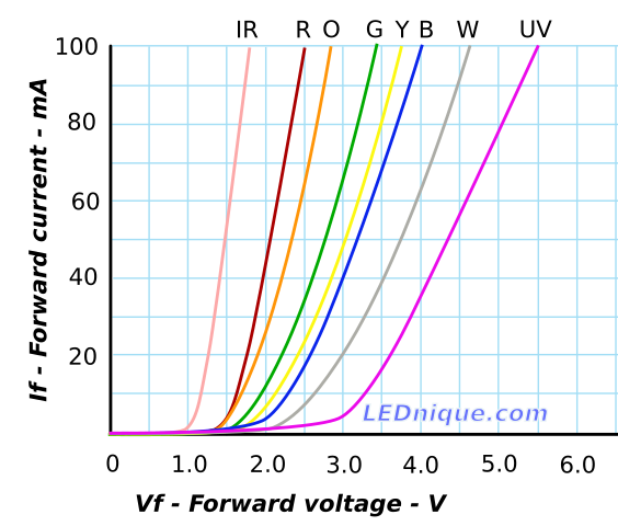
enter image description here

Figure 1. Changing the voltage on the white LED of the graph from 2.5 V to 3.5 V (40%) will increase the current from 6 mA to 40 mA (650%). Source: LED IV curves.

This means that we can assume that over the range of 6 to 40 mA the LED will drop somewhere between 2.5 V and 3.5 V so we might take 3 V as a rough estimate. (You used 3 V in the question so we'll use that.) With a fairly constant 3 V across the LED that leaves 9 - 3 = 6 V across the current limiting resistor. At 300 Ω that will give you 20 mA.

Now if the battery starts to go flat and the voltage falls to 6 V then you will still have roughly 3 V across the LED leaving only 3 V across the 300 Ω resistor resulting in a current of 10 mA.


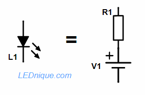
You can improve the mathematical model of the LED by considering it like a voltage source with a series resistor.

enter image description here

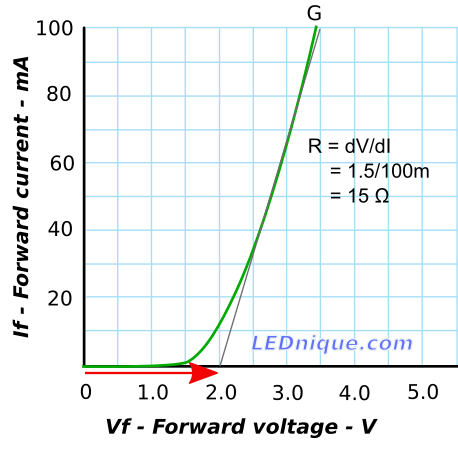
Figure 2. An LED can be approximated as a resistor with a fixed voltage source. Source: Resistance of an LED.

enter image description here

Figure 3. LED equivalent circuit model of the curve in Figure 2.

In the case of Figure 2, V1 = VLED = 2.0 V and RLED = 15 Ω.

If we try these values in our calculations above we get

$$ I_{9V} = \frac {V}{R} = \frac {9-2}{300+15} = 22 \ \text {mA} $$

$$ I_{6V} = \frac {V}{R} = \frac {6-2}{300+15} = 12.7 \ \text {mA} $$

but note that the curve has moved away from the resistance line at 10 mA so the simple model is no longer accurate.

See the linked article for more.

\$\endgroup\$
1
\$\begingroup\$

Yes, there are an infinite number of ways to compute the finite value of \$R=300\:\Omega\$. However, you are actually computing \$R=\frac{V_\text{CC}-V_\text{LED}}{I_\text{LED}}\$. And there is only one way to calculate that in your example case:

$$R=\frac{V_\text{CC}-V_\text{LED}}{I_\text{LED}}=\frac{9\:\text{V}-3\:\text{V}}{20\:\text{mA}}=300\:\Omega\tag{0}$$

Note that for any given voltage source, \$V_\text{CC}\$, and for given values for the LED, you get exactly one way to calculate the resistor's magnitude.

The reality is a little more complex. LEDs vary, one from another, with no two of them exactly alike. The datasheets will specify a range of voltages that may be exhibited by any specific LED (of the same type and manufacture) when a certain current flows through it. This can be quite a range, too. So the value you use for \$V_\text{LED}\$ will only ever be an approximation/average value. You could use the equation with the upper and lower limits and get two different values for \$R\$ and then decide if you want to pick from one or more standard values within that range.


The above formula calculates a resistor (or range of resistor values if you use the datasheet's full specification range of LED voltages.) And the resistor acts as a very rough current regulator regardless of the specific LED within a batch of LEDs from the same family used to calculate that resistor value.

I'm going to use a specific LED datasheet to illustrate how to estimate just how "good" a specific resistor might be in a specific situation, so that you can get a better sense of why a simple resistor works as well as they do and why the exact value of that resistor isn't as critical as you might think.

First, here's the LED: Everlight 5mm white LED. We can see the following entry in that datasheet:

enter image description here

From the above and the formula I mentioned earlier, compute:

$$\begin{align*} \left[\frac{9\:\text{V}-3.6\:\text{V}}{20\:\text{mA}}=270\:\Omega\right]\le R\le \left[\frac{9\:\text{V}-3\:\text{V}}{20\:\text{mA}}=300\:\Omega\right] \end{align*}$$

It's very convenient to select the standard value of \$R=270\:\Omega\$. So let's do that, here.

To compute the quality of regulation using that resistor in this case, let's re-write the equation for the LED so that we can work out the current: \$I_\text{LED}=\frac{V_\text{CC}-V_\text{LED}}{R=270\:\Omega}\$. From that and your voltage source voltage, I think you can easily work out that the range of LED current will be: \$20\:\text{mA}\le I_\text{LED}\le 22.2\:\text{mA}\$.

As you can see, this is pretty good. Assuming the average value of \$V_\text{LED}\approx 3.3\:\text{V}\$, this is about \$21\pm 1\:\text{mA}\$ or about \$21\:\text{mA}\pm 5\%\$. So the resistor, given your supply voltage value, provides pretty good regulation. And it's why a resistor is often "good enough" for many uses with LEDs.

(Note: I didn't take into account here the % variation of the resistor, itself. But these days the values are pretty close to their nominal value. Why don't you do your own calculations using a 2% variation of the resistor value, as well, and see if it changes the results much.)


You can analyze the regulation more generally. Here, you may want to know by what percent will the LED current vary if the power supply voltage varies by some percent value. Or, by what percent will the LED current vary if the current limit resistor itself varies by some percent value. Or, by what percent will the LED current vary if the LED operating voltage varies by some percent value. Those can be interesting questions, at times, depending on what matters.

Those factors are all called "sensitivity figures." How sensitive is one thing relative to another? Let's investigate that question.

This is where the infinitesimal precision of calculus comes into its own. A tiny % variation in current is \$\% I=\frac{\text{d}I}{I}\$ (from a calculus point of view.) Let's start out by applying the derivative operator to the LED current calculation formula from above:

$$\begin{align*}D\left[\: I_\text{LED}\:\right]&=D\left[\:\frac{V_\text{CC}-V_\text{LED}}{R}\:\right]\\\\\text{d}\,I_\text{LED}&=\frac{1}{R}\,\text{d}\,V_\text{CC}-\frac{1}{R}\,\text{d}\,V_\text{LED}-\frac{V_\text{CC}-V_\text{LED}}{R}\,\frac{\text{d}\,R}{R}\end{align*}$$

If we choose to look at the partials (holding the other variations as constant for the purpose), then we find the following three approximations:

$$\begin{align*} \frac{\%\,I_\text{LED}}{\%\,V_\text{CC}}=\frac{\frac{\text{d}\,I_\text{LED}}{I_\text{LED}}}{\frac{\text{d}\,V_\text{CC}}{V_\text{CC}}}&=\frac{V_\text{CC}}{I_\text{LED}\,R}=\frac{1}{1-\frac{V_\text{LED}}{V_\text{CC}}}\tag{1}\\\\ \frac{\%\,I_\text{LED}}{\%\,V_\text{LED}}=\frac{\frac{\text{d}\,I_\text{LED}}{I_\text{LED}}}{\frac{\text{d}\,V_\text{LED}}{V_\text{LED}}}&=-\frac{V_\text{LED}}{I_\text{LED}\,R}=-\frac{1}{\frac{V_\text{CC}}{V_\text{LED}}-1}\tag{2}\\\\ \frac{\%\,I_\text{LED}}{\%\,R}=\frac{\frac{\text{d}\,I_\text{LED}}{I_\text{LED}}}{\frac{\text{d}\,R}{R}}&=-\frac{V_\text{CC}-V_\text{LED}}{I_\text{LED}\,R}=-1\tag{3} \end{align*}$$

Both \$V_\text{CC}\$ and \$V_\text{LED}\$ are positive values (or, at least, the same sign) and also that in order to operate the LED it must be that \$V_\text{CC} \gt V_\text{LED}\$, the following conclusions can be made:

  1. Equation 1 says that regulation vs changes in \$V_\text{CC}\$ is better when \$V_\text{CC}\gg V_\text{LED}\$ and that increases in \$V_\text{CC}\$ will lead to increases in \$I_\text{LED}\$.
  2. Equation 2 says that regulation vs changes in \$V_\text{LED}\$ is better when \$V_\text{CC}\gg V_\text{LED}\$ and that increases in \$V_\text{LED}\$ will lead to decreases in \$I_\text{LED}\$.
  3. Equation 3 says that regulation vs changes in \$R\$ is fixed at 1:1 (but with opposite sign.) So a +1% change in the resistor value will correspond to a -1% change in the current. This is simply because \$R\$ is in the divisor (and that we are talking about small changes in \$R\$.)

Also note that the sensitivity equations can be used without knowing the value of \$R\$. The only thing that matters is the ratio of \$V_\text{CC}\$ and \$V_\text{LED}\$. This is an important observation for resistor regulation: regulation is better when the supply voltage is very much larger than the required load voltage. (Better regulation implies wasting more power by increasing the voltage drop across \$R\$. One of the reasons why active linear regulators were designed, which can provide good regulation without requiring a lot of overhead voltage to get it.)

In your case, but using my datasheet's LED range (\$3.0\:\text{V} \le V_\text{LED}\le 3.6\:\text{V}\$) and therefore choosing the midpoint value of \$V_\text{LED}\approx 3.3\:\text{V}\$, I get \$\frac{\%\,I_\text{LED}}{\%\,V_\text{CC}}=1.58\$ and \$\frac{\%\,I_\text{LED}}{\%\,V_\text{LED}}=-0.58\$. Given the LED datasheet I'd provided, the LEDs are \$3.3\:\text{V}\pm 9\%\$ and so we can compute that a 9% change in \$V_\text{LED}\$ would lead to a \$-0.58\,\cdot\,\pm 9\%= \mp 5.22\,\%\$ change in the LED current. Which is very close to what was observed in earlier calculations above.

\$\endgroup\$
4
  • \$\begingroup\$ I have a stupid question. What values did you use to compute \$\frac{\%\,I_\text{LED}}{\%\,V_\text{CC}}=1.58\$ ? \$3V\$ and \$9V\$ ? \$\endgroup\$
    – G36
    Commented May 2, 2019 at 17:39
  • \$\begingroup\$ @G36 The OP said that \$V_\text{CC}=9\:\text{V}\$ and that \$V_\text{LED}=3\:\text{V}\$. But I substituted in a datasheet to make it real and the LED in that datasheet says \$3.0\:\text{V} \le V_\text{LED}\le 3.6\:\text{V}\$, so I used the midpoint for the calculation, or \$V_\text{LED}=3.3\:\text{V}\$. \$\endgroup\$
    – jonk
    Commented May 2, 2019 at 17:45
  • \$\begingroup\$ Thank for the info. \$\endgroup\$
    – G36
    Commented May 2, 2019 at 17:49
  • \$\begingroup\$ @G36 Although that choice was mentioned earlier in the answer, I just updated the bottom of the answer to re-address your question so that the computation I used should be more immediately clear than it was before. Thanks. \$\endgroup\$
    – jonk
    Commented May 2, 2019 at 17:51

Your Answer

By clicking “Post Your Answer”, you agree to our terms of service and acknowledge you have read our privacy policy.

Not the answer you're looking for? Browse other questions tagged or ask your own question.