1
\$\begingroup\$

schematic

simulate this circuit – Schematic created using CircuitLab

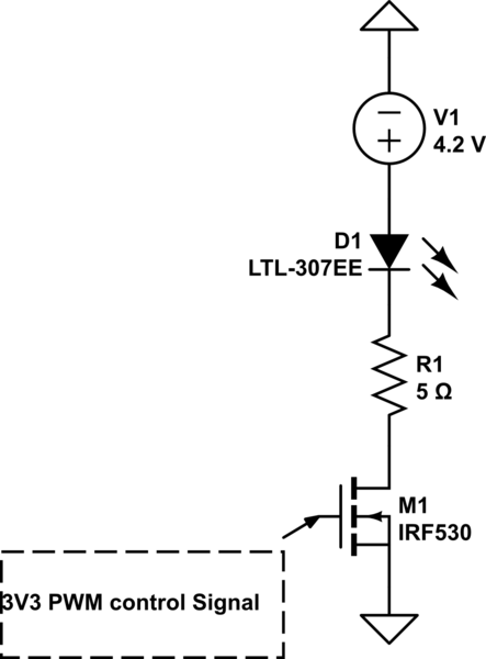
LED: 2.05V @ 350mA 5-6 Ohm Resistor for current regulation

Hi, currently designing a circuit that controls a LED using a PWM logic level signal at 3V3. I am wanting to use a small footprint mosfet or transistor but am unsure what to use. I've looked at MOSFETS but all will operate within the ohmic region of the FET is that okay or will that eventually cause damage to the FET. Am i better to use a BJT transistor to control the switching as its a low voltage low current application but will the switching speed of a BJT be quick enough for a PWM application.

\$\endgroup\$
3
  • \$\begingroup\$ "PWM" doesn't define a speed. You have to tell us how fast you plan to run your PWM for us to tell you if a BJT is too slow. \$\endgroup\$
    – TimWescott
    Commented Oct 11, 2019 at 22:54
  • \$\begingroup\$ I'm guessing here that the \$4.2\:\text{V}\$ source is a lithium battery. It's voltage range over operation probably should be considered. Given the low overhead available here, I don't like the idea of using a resistor for current regulation. You can see part of why I think so by looking here. You probably have enough voltage overhead available for a simple BJT current limiter (two bjts), except for the relatively high current indicated, which suggests instead a BJT + FET as probably preferred. (if you aren't stuck on the resistor idea.) \$\endgroup\$
    – jonk
    Commented Oct 12, 2019 at 4:34
  • \$\begingroup\$ Please update this (at least in the text) with the part number of the actual LED you are planning to use, your depicted LTL-307EE has an absolute maximum of slightly over half of the current you plan to try to force through it. \$\endgroup\$ Commented Oct 12, 2019 at 18:01

3 Answers 3

1
\$\begingroup\$

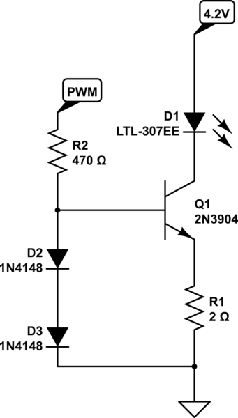
Using a BJT here, with a reasonably well defined Vbe around 0.7V, allows another option : use it as a constant current source. The spread of Vgs values on a MOSFET makes a BJT a better choice for a constant current source. Arrange for the base drive voltage to be around 1.4V, and add a resistor from emitter to GND. As there will be around 0.7V across it, its value (2 ohms 0.5W) controls the LED current (350mA), approximately independent of supply voltage.

For example:

schematic

simulate this circuit – Schematic created using CircuitLab

At 4.2V supply, with 0.7V across the resistor and 2.05V across the LED, theer will be around 1.45V across the transistor ( * 0.35A) = 0.5W dissipation (at 100% duty cycle), so choose an appropriate transistor and heatsinking.

\$\endgroup\$
0
\$\begingroup\$

If you're PWMing an LED to adjust brightness then the frequency required will be too low for the slow switching of a BJT to matter since you could probably do as low as 30Hz-60Hz and get away with it due to the way the human eye works. Even if you used 120Hz it's not going to matter much. For your case, I don't think it matters much which you use, but you'll have lower gate drive current with a logic level MOSFET than an NPN, whereas the NPN can be driven by very base-emitter voltages voltages (almost down to about 0.7V) since it is controlled by the base-emitter current rather than the voltage.

\$\endgroup\$
0
\$\begingroup\$

An NPN transistor that can handle the 350mA current would be a good choice if you have enough drive capability from the 3V3 PWM control signal. Depending upon the transistor gain the base drive current requirement could be 10mA or more. With a NPN transistor you would need to add a series base resistor to limit the current into the base.

There is no reason that you shouldn't be able to use an N-Channel MOSFET as well. It has the advantage of not needing a series gate resistor. You do need to look closely at the gate threshold voltage required to fully turn the part on with a 3.3V signal at the 350mA current level. There are a plethora of FETs available so search to find one with very low On drain to source resistance. If you just pick some garden variety small signal MOSFET you may indeed end up with a part with a higher On resistance.

\$\endgroup\$

Your Answer

By clicking “Post Your Answer”, you agree to our terms of service and acknowledge you have read our privacy policy.

Not the answer you're looking for? Browse other questions tagged or ask your own question.