-1
\$\begingroup\$

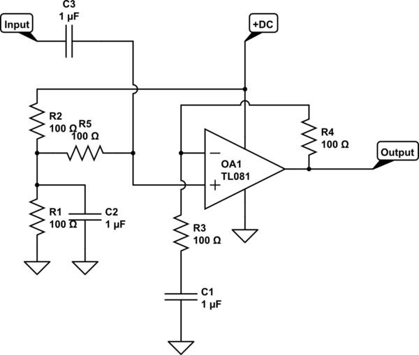
enter image description here

I have a circuit similar to this. I’m trying to lower my noise under 60 Hz. Using pspice I keep finding that I need a very large resistor for R5, like 50 gigs but in practice this is not giving me the low noise I expect. My C3 is fixed at 150 pF. I’m guessing C3 and R5 are forming a low pass filter and that’s why I need a huge resistor, but I made the dc bias current really clean. And actually it’s going through a buffer. There shouldn’t be anything to filter. Why do I need such a big resistor and shouldn’t a big resistor be adding a lot of thermal noise. I don’t know why it’s not working.

Thanks

\$\endgroup\$
5
  • \$\begingroup\$ What is your source {voltage, impedance} and what noise is ambient and why is thermal noise more important? Why is C fixed (tiny brain electrode?) Do you know how to reduce noise with Active guarding and CM rejection? \$\endgroup\$ May 23, 2019 at 1:24
  • \$\begingroup\$ Source is a low noise voltage regulator outputting 3 volts and then divided by 2 with 2 10k resistors to 1.5 volts and then I have it going through a low noise op amp configured as a voltage buffer. Noise is down around -155dbv coming out of the buffer. C is fixed because that’s a different part of the circuit that I can’t modify. I don’t know active guarding and cm rejection \$\endgroup\$ May 23, 2019 at 1:33
  • \$\begingroup\$ C3 and R5, used with C3 in series and R5 in shunt, form a high-pass-filter. And I doubt the TL081 is a low-noise opamp; what are you using? \$\endgroup\$ May 23, 2019 at 3:38
  • 1
    \$\begingroup\$ -155 dBV is almost 100 nVpp and C3 rejects signals below 15kHz while your signals are below 60Hz \$\endgroup\$ May 23, 2019 at 4:43
  • 1
    \$\begingroup\$ It is very annoying that you made a circuit drawing with all resistors being 100 ohms and all capacitors 1uF and then you mention the real values in the text. It is trivial to change the schematic so that it shows the correct values. Especially for noise it is vital that you show an accurate schematic. Browse this site and notice how questions which are written with more care have a better chance of getting a usable answer. \$\endgroup\$ May 23, 2019 at 7:53

1 Answer 1

0
\$\begingroup\$

The total noise across 10 PF cap will be 20uV rms.

The total noise across 150 pF cap will be 20uV * sqrt(150/10) or ~~ 20uV * 4.

\$\endgroup\$

Your Answer

By clicking “Post Your Answer”, you agree to our terms of service and acknowledge you have read our privacy policy.

Not the answer you're looking for? Browse other questions tagged or ask your own question.