4
\$\begingroup\$

I have a collection of piezoelectric transducers that I have got from old devices.

No print stamp on them, and I couldn't get a schematic of the device that could help me to find a datasheet. I wonder if I could find the model through this procedure:

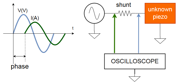
enter image description here

The idea is basically exciting the piezo with a known electrical signal (sine) and measuring the current and voltage in the load. By taking note of the voltage in the shunt resistor I get the current amplitude and phase.

I could say that the piezo impedance equals R+jX, where X is the reactive component.

Is there any pitfall in this idea that I should be aware of? This is the first time I try to model this piezo.

EDIT: i want the model to build a matching network EDIT: The piezos I know, usually work at a simple frequency,so I think that I just need to sample at the same frequency (no freq sweep).

\$\endgroup\$
6
  • 1
    \$\begingroup\$ If you search the web on "piezoelectric transducer equivalent circuit" there are quite some different equivalent circuits which aren't equivalent to each other... \$\endgroup\$
    – Huisman
    Commented Jun 4, 2019 at 8:09
  • 1
    \$\begingroup\$ @Huisman good point! Any model is only good for modeling something for a specific purpose: For example, a model of a metal bridge might be very different for the purposes of someone making sure it's safe to run a train across from the model of the same class of bridges used by someone for the purpose of designing ship radars. Ramiro, is it fair to assume you care about the parameters of these Piezos for the purpose of making them generate sound waves of a single frequency? \$\endgroup\$ Commented Jun 4, 2019 at 8:14
  • 1
    \$\begingroup\$ Correct me if I'm wrong, but I don't think that R+jX contains enough information to model it as Bimpelrekkie's crystal model. So my bets are on making a bode plot and then using regression (with least squares for an example) to spit out Lm, Cm, Rm and Co. \$\endgroup\$ Commented Jun 4, 2019 at 8:54
  • 1
    \$\begingroup\$ Edited to add details \$\endgroup\$ Commented Jun 4, 2019 at 15:46
  • 1
    \$\begingroup\$ @RamiroVargas In that case I think you're on the right track. \$\endgroup\$ Commented Jun 5, 2019 at 4:53

1 Answer 1

3
\$\begingroup\$

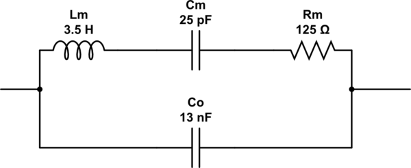
A simplified model of a piezo resonator is similar to the model of a crystal (the ones used in crystal oscillators).

The circuit for both are the same but the component values are different.

This is an example of a model for a piezo element:

enter image description here

Note how Cm is much smaller (500 times smaller) in value than Co. This makes it somewhat difficult to determine the values of the LCR series circuit.

The issue is this: the LCR series circuit resonates at a certain frequency (in the circuit above this is at 17 kHz). At lower and higher frequencies that this resonance frequency the circuit will just measure as if it is only the capacitor Co (13 nF). Additional to that the frequency band for which you will see that resonance is very narrow, possibly only a few Hz so it can be quite a challenge to "find" that resonance and even when you find it you will need an extremely frequency stable signal generator to be able to do accurate measurements.

Professionals would use a "network analyzer" for this. I have used these in the past and with these it is just a matter of selecting the circuit topology (so I select a circuit similar to the one shown above) and setting the right frequency sweep. Then the Network analyzer will determine the circuit's component values. Unfortunately Network analyzers are in the range of: if you have to ask what it costs, you cannot afford it.

I suggest you read this question and answer and also this article about models of crystals.

\$\endgroup\$
6
  • 1
    \$\begingroup\$ ah! so, good models exist, but they've got hard to determine parameters. In this case, since the bandwidth of this thing is rather limited: Wouldn't a wideband/white excitation signal coming from a soundcard make a rather nice test signal, and a soundcard line input make a rather nice digitizer? One could make a rather long recording to achieve near-perfect frequency resolution. \$\endgroup\$ Commented Jun 4, 2019 at 8:59
  • 1
    \$\begingroup\$ @MarcusMüller Assuming the resonance is at 17 kHz: if this would work might depend on how "good" the signal from a soundcard is at 17 kHz. I doubt if a soundcard can make a "jitter free" 17.000 kHz and also 17.001 kHz. My feeling is that we'd need a DDS for this. \$\endgroup\$ Commented Jun 4, 2019 at 9:05
  • 1
    \$\begingroup\$ You wouldn't need to make the tones isolatedly – a sufficiently long pseudo-white signal would contain both frequencies (and frequencies between at a resolution only limited by the length). \$\endgroup\$ Commented Jun 4, 2019 at 9:07
  • 1
    \$\begingroup\$ However, the jitter aspect is an interesting one: jitter / phase noise of course tend to slightly shape noise. However, since we're really not doing coherent detection, but would just be observing the output spectrum as a whole, I'd doubt that at the resonant frequencies, that slight amplitude distortion really matters for identification purposes. \$\endgroup\$ Commented Jun 4, 2019 at 9:08
  • 1
    \$\begingroup\$ however, you're right, every audio device will probably have their analog cut off at around 16 kHz. \$\endgroup\$ Commented Jun 4, 2019 at 9:09

Your Answer

By clicking “Post Your Answer”, you agree to our terms of service and acknowledge you have read our privacy policy.

Not the answer you're looking for? Browse other questions tagged or ask your own question.