1
\$\begingroup\$

What is the proper way of repeating I2C/SPI blocks?

Since we know in the case of SPI blocks, MISO, MOSI & SCK must all be tied together in a single bus for communication to happen.

I have read the similar question on this forum regarding this issue but didn't found the answer satisfactory. The person who asked the question only had to place the block 3 times, so putting them directly on schematic made sense.

But in my project, I need 6-7 similar blocks for I2C and SPI. I don't know exactly at this point so using Repeat will be very beneficial for me in the long run.

Here is my top sheet:

enter image description here

I have successfully made Chip Enable into bus since they are all unique. But I need to tie the MISO/MOSI/SCK together for all repetitions.

Also I am getting these errors currently: enter image description here enter image description here

A generic answer on how to connect multiple SPI/I2C blocks together would be really appreciated. Or a definitive one that this is not possible.

Thank you for your help.

\$\endgroup\$
2
  • \$\begingroup\$ I started to make an answer, but then I ran into the Unique Identifiers Errors, and then ran out of ambition and gave up. However, to get around the multiple Output Sheet Entries Error, redefine MISO ports and the Sheet entries to not be the Output type, as by default, one should not tie multiple output lines together (as defined in the default connectivity matrix in Project Options). Use 'Unspecified' for the Sheet Entry Type instead, as it more closely mimics the Open-Drain nature of unaddressed SPI chips. The Sheet entry type can be modified in the object's properties. Good luck! \$\endgroup\$ Commented Jun 6, 2019 at 19:10
  • \$\begingroup\$ Hi! Thanks for your interest in solving this problem. Yes the 'Unspecified' for sheet entry solved the "MISO contains multiple output" problem. But the real problem of repeating these safely is still at large :( \$\endgroup\$ Commented Jun 7, 2019 at 16:06

1 Answer 1

3
\$\begingroup\$

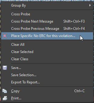
Since Altium is unaware of the chip configuration or output driver type, it is not possible to connect more than one sheet entry outputs to one net. I'm usually solving this error by placing a "specific No ERC for this violation" from the messages panel after I ran the DRC.

enter image description here

I prefer this over using "unspecified" sheet entries because it is clearer in documentation. It keeps the schematic readable also on a print out. Neither would I disable this rule check altogether, because one might miss a problem somewhere else.

\$\endgroup\$

Your Answer

By clicking “Post Your Answer”, you agree to our terms of service and acknowledge you have read our privacy policy.

Not the answer you're looking for? Browse other questions tagged or ask your own question.