3
\$\begingroup\$

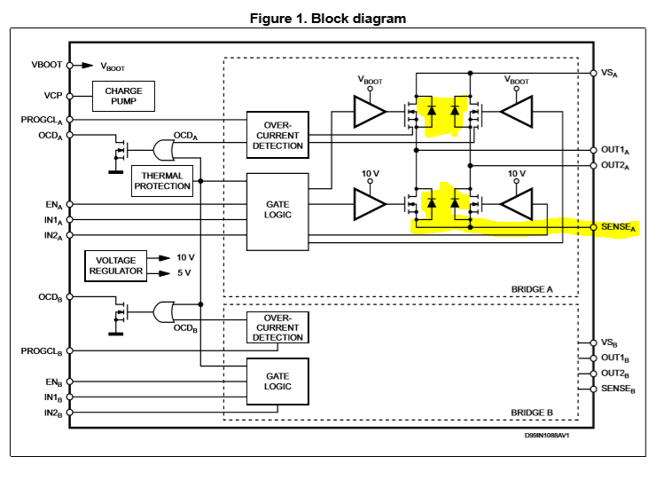
We're building a motor-drive circuit using an L6206 dual H-bridge circuit. The bottom side of its H drivers come out of a pin called \$V_{sense}\$, intended to be connected to ground or to a low-side current-sense circuit. I'm expecting to drive motors with PWM up to an amp or two.

I want a logic sense line to indicate whether there's any current flowing (say \$>10mA\$), or not. It's essentially detecting the operating presence of the (removable) motor.

I think I can do this by comparing the voltage drop across a Schottky diode with an approx \$0.25V\$ reference. I'm thinking of using a divider to create a weak \$0.25V\$ voltage source from my \$5V\$ power supply, a \$2A\$ Schottky diode (eg SB240, \$V_f=0.5V\$ at \$2A\$) with a small \$25\Omega\$ bypass resistor to eat any leakage, and a comparator (eg LM324 op-amp, or LM339) to create the \$5V\$ logic result.
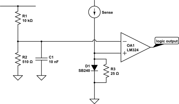
schematic

simulate this circuit – Schematic created using CircuitLab

Wherever I have looked up designing current sense circuits, there is always a low-value power resistor to create the voltage drop. I haven't found any that use a diode. I think that a Schottky diode is perfect: its voltage drop will clamp off nicely so it won't waste heat, it's cheap and simple.

Perhaps everyone else is interested in measuring the current level, where I just want to know if there is a current at all? Or, they only care about being close to a maximum current, where I want a minimum?

Why don't I see any diode-based current sensors?

Note: my logic output essentially goes into a latch, so I don't care that the signal will flap around with the PWM.

\$\endgroup\$
3
  • 7
    \$\begingroup\$ It’ll certainly waste more heat than a low impedance resistive current shunt and amplifier and, it won’t be linear. Sounds a bad idea to me. \$\endgroup\$
    – Andy aka
    Commented Jul 27, 2019 at 16:16
  • 1
    \$\begingroup\$ You could reduce the bypass resistor from 25 to about 2 ohms (using a cheap comparator whose offset voltage is 10mV, sensing your 10mA decision point). Yes, the diode will clamp on big currents - its a design decision: is diode cost worth the efficiency increase? \$\endgroup\$
    – glen_geek
    Commented Jul 27, 2019 at 17:17
  • 2
    \$\begingroup\$ @Andyaka Ok, I think I don't want it to be linear - I want it to snap over at around 10mA (give or take) and stay there all the way up. If I use a little \$0.2\Omega\$, it means I need to detect a 2mV gap for my 10mA trigger: might that be quite challenging with noisy power PWM and motors just next door? and it still drops \$800mW\$ at the max 2A, about same as the diode. I can make the resistor lower, but the sensitivity requirements get harder... \$\endgroup\$
    – SusanW
    Commented Jul 27, 2019 at 17:31

4 Answers 4

4
\$\begingroup\$

Using diodes of any form to detect an open circuit motor or wiring is not going to give good results.
As others have mentioned, there are temperature variations to handle for the diode, and using a resistor is difficult when the voltage drop becomes very small.

However more important than any of the above you would have to use a pair of back to back diodes or you will compromise the back EMF handling of the H-Bridge and risk damaging the device.

enter image description here

Notice that the sense line is the bottom of the H-bridge and if you allow the voltage to get too high you may impact the ability to drive the lower FETs. You also need a low resistance path to ground to allow back-EMF clipping to occur.

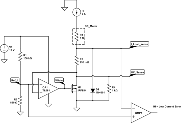
There are multiple ways to provide BOTH open circuit detection and maintain current sensing, and I'll show one way to do it here:

schematic

simulate this circuit – Schematic created using CircuitLab

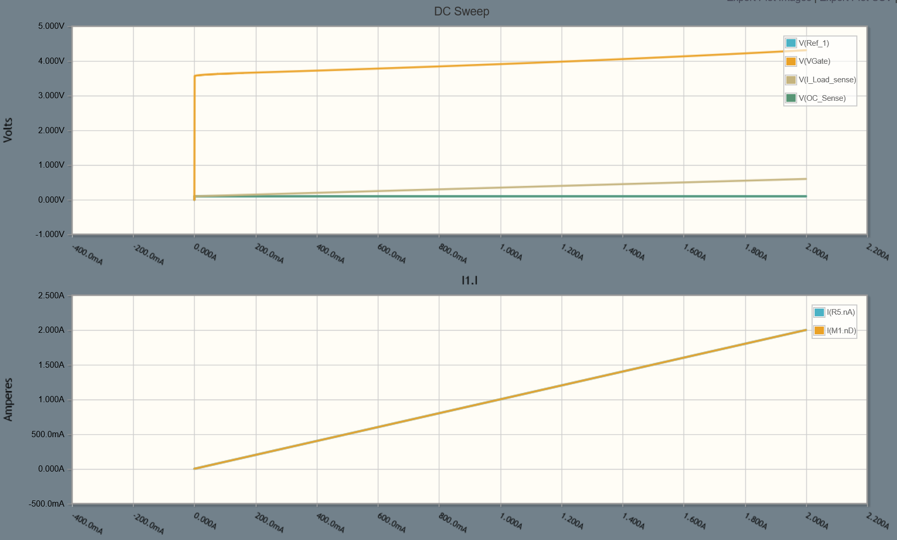
Waveforms would look like this for a 2A span:

enter image description here

In the schematic above:

  1. R1/R2 create a reference voltage of about 100mV
  2. R4 starts the OA1 driving M1 gate
  3. M1 (operating in a linear mode) maintains a 0.1V plateau providing there is at least 100uA current flowing
  4. If there is no current flowing then R4 pulls both OC_Sense and I_Load_Sense low
  5. CMP1 creates an Error signal by comparing I_Load_Sense to the Ref_1 voltage
  6. R5 provides normal load current sense by subtracting Ref_1 from I_Load_Sense
  7. D1 prevents the lower point in the H-Bridge exceeding about 1.1V (probably not required)

Considerably more complex than using a single diode, but provides open circuit detection and current measurements for the H-Bridge.

UPDATE: In the schematic above the parts selected were just what was readliy avaialble in the simulator. They were not meant to indicate an absolute selection for the application.

FET selection
The example I used in the schematic is very large, it was just what was selected in the simulator, and was used only because of its threshold voltage.
Since the current for the application is about 2A, then any FET with a low VGS(th) rated for adequate current would be viable.
My current PCB favorites are the AO3400 and AO3401 ….cheap and with great characteristics. Your total dissipation in this application is about:
2 * 0.1 --> 200mW and the package is rated to about 0.9W @ 70degC, so it should be happy at up to 2-3A motor current. Again in the circuit I used 12V to feed the opamp and FET …...with low VGS(th) FETs you could use just 5V to drive the opamp and FET.

Opamp
I used the TL081 again just because it was there. Any rail-rail opamp that work at 5V and above be ideal for this application. The TL081 would not be a great selection for a 5V rail of course since it's not rail-rail output.

I tend to use the TLV9001/TLV9004 for MCU input signal processing, and they may be a good selection here if you want to use a 5V supply.

For 12V or higher you might consider the TLV9101/TLV9104 which would be viable up to 16V. (I have not tried these myself).

\$\endgroup\$
6
  • \$\begingroup\$ First - thanks very much for the great answer: hadn't noticed the back EMF issue, oops! Now I'm studying your circuit - very interesting. How does the back EMF flow through this? Looks like it mostly goes back up through the MOSFET, is that right? \$\endgroup\$
    – SusanW
    Commented Jul 29, 2019 at 10:17
  • 1
    \$\begingroup\$ @SusanW The back-EMF indeed flows through the FET intrinsic diodes. The circuit I showed simply ensures you have a diode in the same polarity to allow clipping to the ground. \$\endgroup\$ Commented Jul 29, 2019 at 14:21
  • 1
    \$\begingroup\$ @SusanW The real problem with using JUST a current sense resistor is that to detect low current ….say 10mA across a 500m Ohm resistor (2.5mV) you need very large gains and then noise becomes a problem. By adding a fixed offset you provide a clear signal level (100mV in the case above) so need only a comparator to generate your Error condition indicator. PS....the FET I showed was for demonstration only, you'd use a small SOT-23 FET in practice. \$\endgroup\$ Commented Jul 29, 2019 at 14:27
  • \$\begingroup\$ :-) :-) Glad you added the final note about the FET! We were going "55V 41A? What a monster! What have we got ourselves into?" - but any FET that can handle 2+ amps is fine, I guess, as long as it has an intrinsic diode. Ok, so it's been the noise I've been scared of, with regards to mV levels. Is there anything special about the choice of the TL081, btw? I'm going to end up with 8 of these sense circuits, so I'm thinking about quad-packs, but that'd sacrifice the fine tuning offsets on the op-amps... \$\endgroup\$
    – SusanW
    Commented Jul 29, 2019 at 20:03
  • 1
    \$\begingroup\$ @SusanW Sorry if I scared you, the device selections were based purely on the inbuilt editor/simulator. I've updated the answer to provide more direction, though the parts are up to you. \$\endgroup\$ Commented Jul 29, 2019 at 20:52
7
\$\begingroup\$

You can choose the resistor so that it consumes the same power, or less if you want to. At 2 A the diode will consume 1 W, so "equal" resistor would be 0.25 Ω. At smaller current, say 1 A, the diode will consume roughly 0.5 W because the voltage doesn't drop that much. There the resistor only consumes 0.25 W, which is significantly less.

The diode is not accurate. Its \$V_f\$ varies especially with temperature. Junction to ambient thermal resistance is 45°C so you can expect that much heating with the maximum current. And if you have some heating from outside (direct sunlight for example) you can easily reach 100°C temperature for the junction which drops \$V_f\$ to half from the original. A decent resistor drifts something like 50 ppm/°C, so at temperature rise from 25°C to 100°C the resistance changes only 0.375%

With a resistor you do need an amplifier, because at low current the voltage is also low. But there are circuits made for just that, so implementation is not difficult. Search for e.g. current sense amplifier. Some of those even have a built in comparator so the number of components might even be the same as with the diode + comparator solution. And while you are adding an amplifier, you can drop the resistor size, and get away with a lot less power loss than with the diode.

So the answer to your question is, diode based solutions are not accurate, and consumer more power compared to shunt resistor solutions.

\$\endgroup\$
1
  • \$\begingroup\$ Your point about the temperature is excellent - I'd thought about whether the heat was excessive but I'd carelessly assumed the effect on \$V_f\$ to be negligible. And I notice that some current sense amps discuss PWM immunity - interesting. Ok, brilliant - thanks, good answer. I'll leave it a couple of days to give others a voice, but ... yep, thanks :-) \$\endgroup\$
    – SusanW
    Commented Jul 27, 2019 at 18:17
2
\$\begingroup\$

Change the idea. You can insert an active low current pulse circuit to detect if there's a load connected. If the voltage depends enough on the pulses, there's no load.

\$\endgroup\$
0
\$\begingroup\$

The request is to see if the motor is plugged in or not, yes?

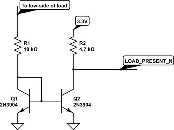
I faced a similar problem for a product, to detect if a display panel was plugged in. My solution? Use a current mirror to pass a small sensing current into the load, like so:

schematic

simulate this circuit – Schematic created using CircuitLab

Q1 sinks a small current from the connected load, turning on Q2 and bringing signal LOAD_PRESENT_N low. If there is no load connected, Q1 and Q2 will be off, so LOAD_PRESENT_N will be high.

Ideally you want to use a matched pair for Q1/Q2, but for this kind of basic use separate NPNs should be ok.

EDIT: add to the above: a weak pull-up to the load (+) side to complete the low-current sense circuit. The sensing would only be used when the motor is idle, such as during initial power on or during a diag self-test.

Also note that the sensing connections are to the motor, not to the Rsense on the H-bridge low side. You still need Rsense for the error amplifier, and it should be a low value (like 0.1 ohm or so) to minimize power loss.

\$\endgroup\$
8
  • \$\begingroup\$ Looks good, but how does this detect 10mA, when the full flow of the motor is up to 2A? I think that \$10k\Omega\$ is in series with the load, isn't it? \$\endgroup\$
    – SusanW
    Commented Jul 30, 2019 at 9:29
  • \$\begingroup\$ It’s not intended to sense the entire current. It is in parallel with the driver, and works when the driver is ‘off’. You would also have a weak pull-up on the high side of the load. \$\endgroup\$ Commented Jul 30, 2019 at 15:05
  • \$\begingroup\$ Mm, I see ... ok, I have a full H-bridge and the load is reversible, so I guess I could arrange a bridge rectifier around the load. Though (not previously mentioned) I'm looking for a disconnection condition too; I guess I could briefly kill the power, and then sense ... might have to wait for the motor to spin down though. \$\endgroup\$
    – SusanW
    Commented Jul 30, 2019 at 15:56
  • \$\begingroup\$ You don’t need a bridge rectifier. You’re only injecting a small sense current, which you would check when the motor is idle, e.g., at start-up, during some sort of diag routine or when the motor is idle. \$\endgroup\$ Commented Jul 30, 2019 at 16:09
  • \$\begingroup\$ My experience with servos (daisywheel printers) is that such a fault - open to the motor - would be detected in two ways: failure to index the servo at initialization, and failure to respond properly to a commanded velocity. In either case a timeout would be issued to put the servo in ‘check’ (disable). This mechanism would be coupled with mechanical safety interlocks to protect the operator. Also, the motor link should also include a fuse: few things are more exciting than a runaway high-power motor slamming hard against a stop. \$\endgroup\$ Commented Jul 30, 2019 at 18:50

Your Answer

By clicking “Post Your Answer”, you agree to our terms of service and acknowledge you have read our privacy policy.

Not the answer you're looking for? Browse other questions tagged or ask your own question.