4
\$\begingroup\$

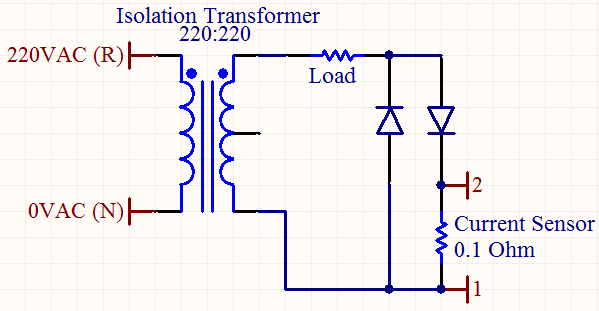
I have an experimental circuit like below:
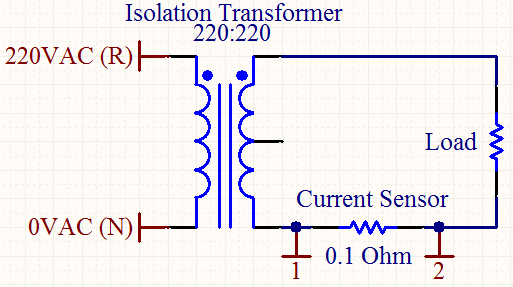
Experimental Circuit

My aim is to measure maximum or effective value the current on the load.
The current sensor is a simple \$ 0.1 \Omega \$, \$5W\$ resistor.

I filtered the voltage on the current sensor with the following cascaded RC filter:
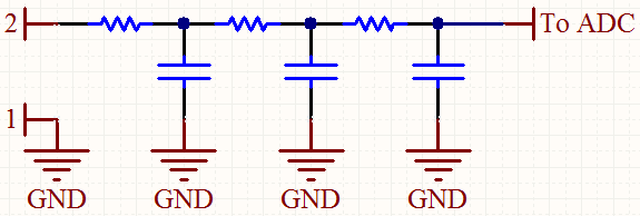
3rd Order Passive RC Filter

The output of the filter show no signal (\$0V\$). This was an expected result since I was applying a sinusoidal signal to filter like this.

I can't use a diode at the filter stage since the voltage on the current sensor is at the level of millivolts.

Is there any simple trick for reading the voltage on the current sensor? If possible, I don't want to change the main structure of this circuit too much.


EDIT:

How about this alternative circuit?
Alternative Circuit

Assuming that both alternances of the AC signal have the same shape on load, I can calculate the current on the load by only considering the positive alternance.


Notes:

  1. AC frequency is 50Hz.
  2. I'm using the transformer to protect my oscilloscope.
  3. At the filter stage, all resistors and capacitor have the same values (\$R=100k \Omega , C=1 \mu F\$).
  4. The ADC is on a microcontroller (maybe I can add an opamp beforehand for scaling), so I can do any algebraic manipulations on the sensed value.
  5. The load is generic. I want it to be as wide range as possible. I'm using a \$60W\$ lamp for this experiment.
\$\endgroup\$

2 Answers 2

3
\$\begingroup\$

Another reason (apart from being a symmetrical signal) for not getting a reading is that the voltage across the sensing resistor is too low. A 60W bulb at 230V gives 250mA. Across a 0.1\$\Omega\$ resistor this results in just 25mV. You'll need an amplifier, which can be as simple as a basic opamp circuit.

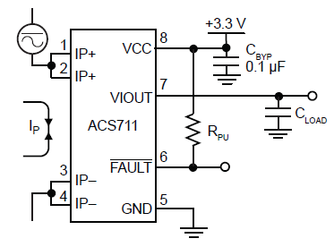
Another solution would be to use a Hall effect sensor. Not only can the Hall effect sensors do with mV/A losses, but sensors like Allegro ACS711 can handle high currents and have amplification built-in.

enter image description here

For the ACS711 sensitivity is 110mV/A. For currents like several amperes you can supply this signal directly to the ADC, if you want to measure also lower currents you need an external amplifier.

\$\endgroup\$
3
\$\begingroup\$

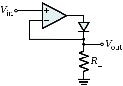
There are a couple of ways to handle the symmetrical signal. As you noticed, the voltage drop of the diode is pretty large in comparison to the signal. What you'd prefer is an ideal diode with zero voltage drop. It's actually quite easy to make such a super diode. You just have to add an OpAmp to the compensate for the voltage drop:

Super Diode

You'll then have to buffer Vout with another OpAmp, wired for some gain.

The other thing you might like to do is create a peak detector. This will hold the output voltage at the peak current value. Just add a capacitor in parallel with RL.

\$\endgroup\$
1
  • \$\begingroup\$ half wave rectifiers are good, but full-wave rectifiers are better, and rms detectors are even better than that. the difference is due to noise/crest factor issues. \$\endgroup\$
    – Jason S
    Commented Apr 4, 2012 at 13:57

Your Answer

By clicking “Post Your Answer”, you agree to our terms of service and acknowledge you have read our privacy policy.

Not the answer you're looking for? Browse other questions tagged or ask your own question.